A driving device for automatic inspection and positioning of safety injection pipes of reactor pressure vessels

A pressure vessel and automatic inspection technology, which is applied to the monitoring of reactors and nuclear reactors, and the reduction of greenhouse gases, etc., can solve the problems of affecting the detection results, troublesome dismantling, and difficult root cleaning, etc., to achieve accurate positioning, tight and reliable effects

Active Publication Date: 2019-01-08
RES INST OF NUCLEAR POWER OPERATION +1
View PDF7 Cites 0 Cited by
  • Summary
  • Abstract
  • Description
  • Claims
  • Application Information

AI Technical Summary

Problems solved by technology

Since the pipe near the pressure vessel is wrapped with an insulation layer, it is troublesome to dismantle it. At the same time, the dose rate of the external environment is relatively high, so it is difficult to detect from the outside
Therefore, the inspection can be carried out from the inside of the pipe, but the ultrasonic inspection from the inside is divided into contact ultrasonic inspection and water immersion ultrasonic inspection. Since the internal weld seam of some small-diameter pipes is not easy to clean after welding, the weld left on the inner wall Slag, if contact ultrasonic testing is used, the fit of the probe cannot be guaranteed, which will affect the test results, and the probe holder may be stuck at the same time.
[0003] At present, there are already relevant ultrasonic automatic inspection devices for pipeline water immersion in China, and the number of welds to be inspected is relatively simple.

Method used


Image

  • A driving device for automatic inspection and positioning of safety injection pipes of reactor pressure vessels
  • A driving device for automatic inspection and positioning of safety injection pipes of reactor pressure vessels
  • A driving device for automatic inspection and positioning of safety injection pipes of reactor pressure vessels

Examples


Embodiment Construction

[0033] The present invention will be described in further detail below in conjunction with the accompanying drawings and specific embodiments.

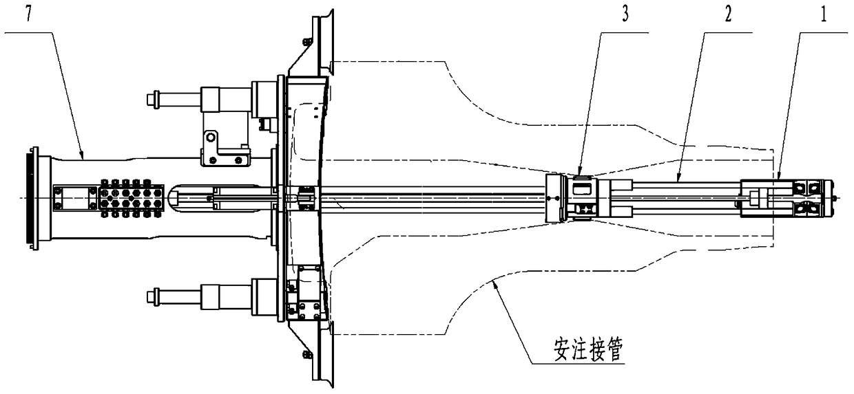
[0034] Such as figure 1 As shown, the reactor pressure vessel safety injection pipe automatic inspection and positioning driving device includes a main movement assembly 7 at the rear end, an intermediate support assembly 3 at the front end, an axial assembly 2 at the safe end, and an inspection assembly 1 at the safe end.

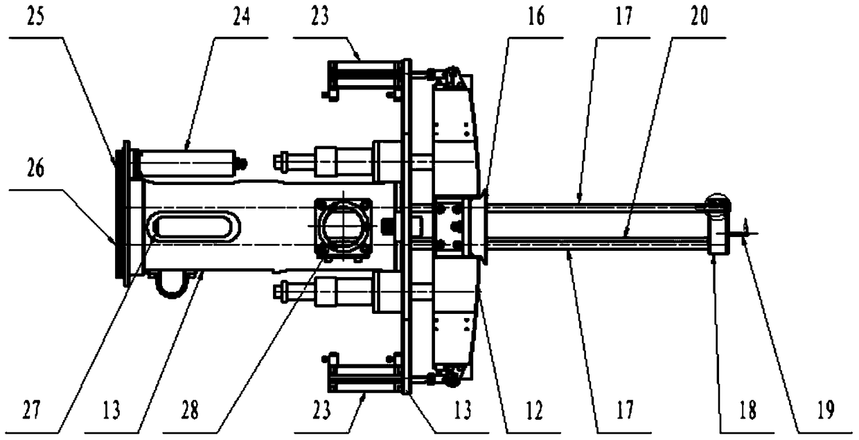
[0035] As shown in Figure 2, the main motion assembly 7 is installed with a peripheral motion driving gear 25 and a peripheral motion driven gear 26 at the rear of the main motion sleeve 13, and a peripheral motor 24 and an axial motor 24 are installed on the main motion sleeve 13. motor27.

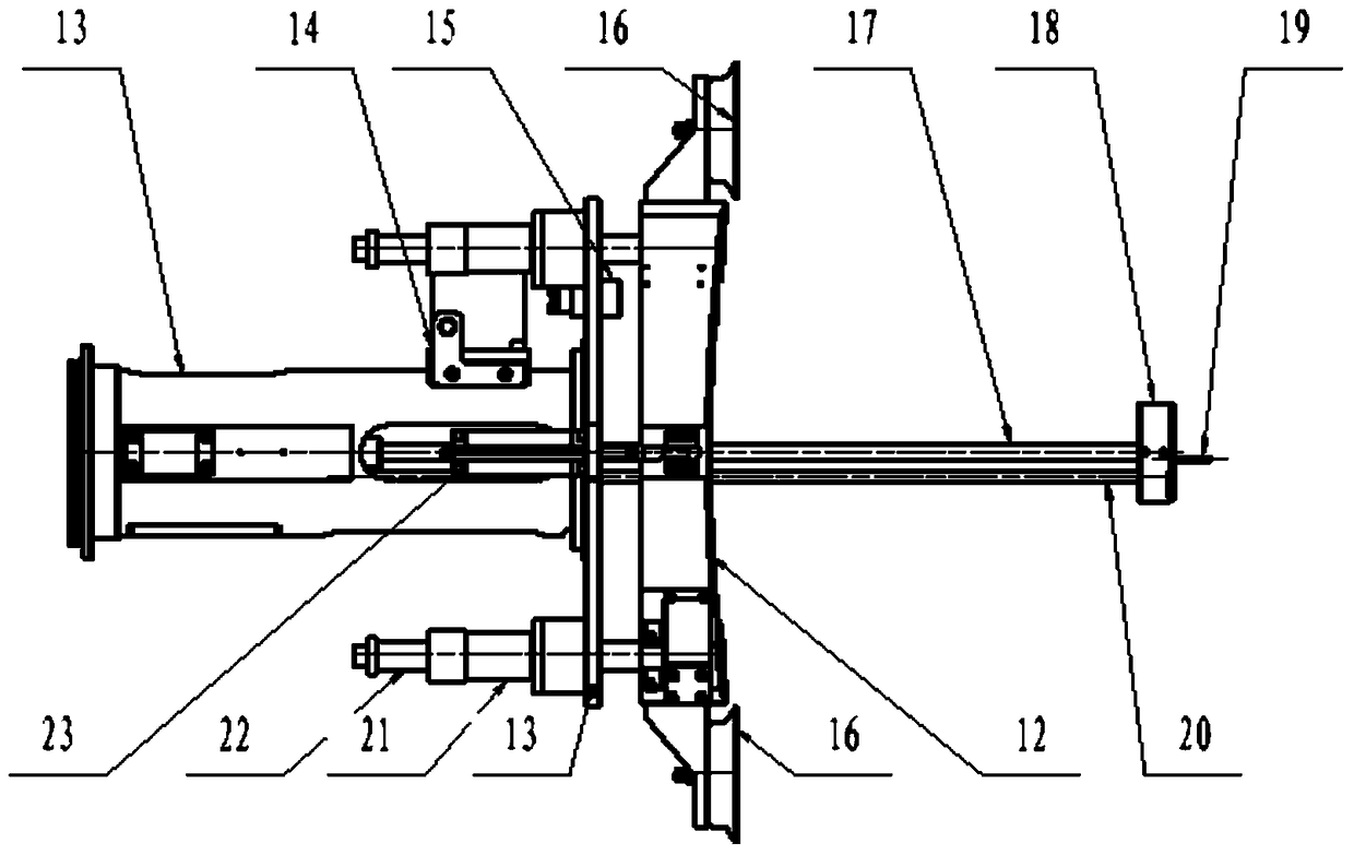
[0036] The stretching cylinder 23 installed at the front end of the main movement sleeve 13 and the fixed mount 12 are installed in the circumferential direction, and the piston rod of the stretched cylinder 23 passes throug...


PUM


Abstract

The invention belongs to a nuclear power station non-destructive testing technology, and particularly discloses an automatic checking, positioning and driving device for a safety injection pipe of a reactor pressure vessel. The device comprises a main movement assembly, a middle supporting assembly, a safe end axial assembly and a safe end checking assembly, wherein the middle supporting assembly, the safe end axial assembly and the safe end checking assembly are sequentially connected with the main movement assembly. The main movement assembly comprises a main movement sleeve, a circumferential movement driving gear, a circumferential movement driven gear, a circumferential motor and an axial motor. The middle supporting assembly comprises a middle supporting sleeve and a middle supporting central spindle; the safe end axial assembly comprises a safe end rear supporting base, a safe end front supporting base, a safe end guide shaft and a safe end screw. The axial motor is designed to drive the main movement assembly and the safe end axial assembly to move in the axial direction. The axial movement range of the main movement assembly is inconsistent with that of the safe end axial assembly so that two movement ends can be different in axial speed through the difference of the main movement screw lead and the safe end screw lead, and the connection pipe supersonic checking requirements and the extra segment supersonic testing requirement are met.

Description

technical field [0001] The invention belongs to the non-destructive detection technology of nuclear power plants, and in particular relates to a driving device for automatic inspection and positioning of safety injection pipes of pressure vessels. Background technique [0002] There are different pipes on the nuclear reactor pressure vessel. According to the requirements of relevant specifications, regular non-destructive testing of the welds of these pipes is required. Since the pipe near the pressure vessel is wrapped with an insulation layer, it is troublesome to dismantle it. At the same time, the dose rate of the external environment is relatively high, so it is difficult to detect from the outside. Therefore, the inspection can be carried out from the inside of the pipe, but the ultrasonic inspection from the inside is divided into contact ultrasonic inspection and water immersion ultrasonic inspection. Since the internal weld seam of some small-diameter pipes is not e...

Claims


Application Information

Patent Timeline
Patent Type & Authority Patents(China)
IPC IPC(8): G21C17/017
CPCG21C17/017Y02E30/30
Inventor 吴东栋陈姝张志鹏张军
Owner RES INST OF NUCLEAR POWER OPERATION
Why Eureka
Try Eureka