Display method and system
A display method and interface display technology, applied in the direction of instruments, electrical digital data processing, data processing input/output process, etc., to achieve the effect of enriching visual effects, increasing the area of display and operation, and improving pertinence
- Summary
- Abstract
- Description
- Claims
- Application Information
AI Technical Summary
Problems solved by technology
Method used
Image
Examples
Embodiment 1
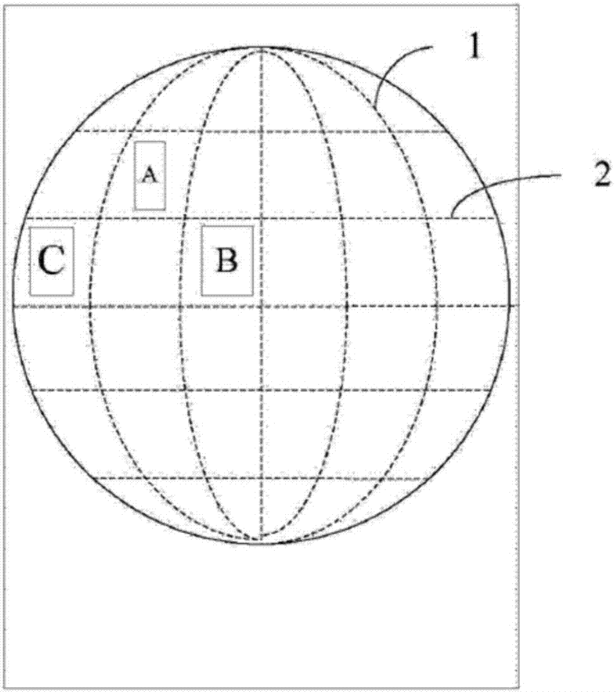
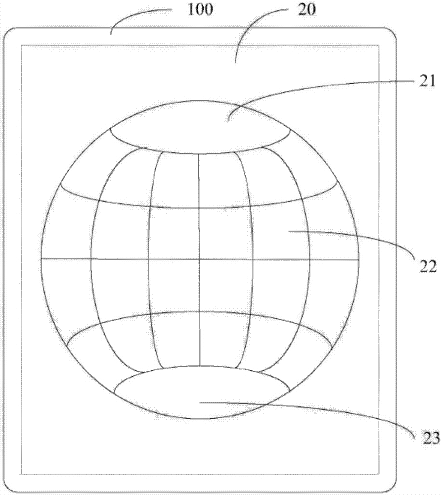
[0065] In this embodiment, a display system applied to an electronic device with a circular desktop includes a modeling module, a display module and a switching module. Wherein, the modeling module is used to build a spherical model and arrange application icons on the spherical model; the display module is used to display the first interface on the circular desktop, and the first interface displays the corresponding current application program on the spherical model And during the sliding operation, a second interface is displayed on the circular desktop, and the second interface displays the sliding progress relationship currently applied on the spherical model; the switching module is used to switch applications according to the sliding track of the sliding operation input by the user. The modeling module includes a storage unit, an acquisition unit and a calculation unit, wherein the storage unit is used to store the application program of the electronic device; the acquisi...
Embodiment 2
[0086] Such as Figure 8 As shown, on the basis of Embodiment 1, setting the progress bar as a progress ring can also be used to display the sliding progress. At this time, the method of determining the position of the cursor area representing the current application program position on the circle is as follows:
[0087] 1) Research on the sliding action around the X axis;
[0088] 2), projecting the application icon onto the Y-Z plane in the coordinate system;
[0089] 3), connect the origin of the coordinate system and the outer edge of the projected figure to obtain the included angle θ;
[0090] 4), calculate the arc length l corresponding to the included angle θ in the progress ring: l=θπr / 180, where r is the radius of the progress ring;
[0091] 5), taking the positive direction of the Y-axis on the Y-Z plane as the reference direction, and based on the position of the included angle θ on the Y-Z plane, determine the position of the cursor interval on the progress axi...
Embodiment 3
[0095] On the basis of Embodiments 1 and 2, if the number of meshes M of the spherical model to be constructed is large, selecting the cursor point to represent the position of the current application can ensure the display effect of the display interface. Such as Figure 10 As shown, in this embodiment, if the progress unit is a progress ring, the optional method for determining the position of the cursor point representing the current application position on the ring is as follows:
[0096] 1) Research on the sliding action around the X axis;
[0097] 2), projecting the application icon onto the Y-Z plane in the coordinate system;
[0098] 3) Connect the origin of the coordinate system with the center point of the projected graphics and extend to intersect with the ring;
[0099] 4), taking the positive direction of the Y axis on the Y-Z plane as the reference direction, based on the position of the intersection point, determine the position of the cursor interval on the p...
PUM
 Abstract
Description
Claims
Application Information
 - R&D
- Intellectual Property
- Life Sciences
- Materials
- Tech Scout
- Unparalleled Data Quality
- Higher Quality Content
- 60% Fewer Hallucinations
Browse by: Latest US Patents, China's latest patents, Technical Efficacy Thesaurus, Application Domain, Technology Topic, Popular Technical Reports.
© 2025 PatSnap. All rights reserved.Legal|Privacy policy|Modern Slavery Act Transparency Statement|Sitemap|About US| Contact US: help@patsnap.com


