Eureka AIR delivers breakthrough ideas for toughest innovation challenges, trusted by R&D personnel around the world.

Automatic plug wire testing device

A test device and automatic plug-in technology, applied in the direction of measuring devices, measuring electricity, measuring electrical variables, etc., can solve the problems of poor HDMI signal test effect, inability to realize test automation, and poor signal transmission, so as to save manpower and improve Efficiency and effect, the effect of improving test efficiency

Active Publication Date: 2017-07-04
QISDA SUZHOU
View PDF8 Cites 5 Cited by
  • Summary
  • Abstract
  • Description
  • Claims
  • Application Information

AI Technical Summary

Problems solved by technology

However, through the existing technology, due to the small contact area between the probe and the contact, if the contact is inaccurate or the displacement is deviated, the signal transmission will be poor, and the existing technology relies on manual insertion for alignment, which cannot The automation of the test is realized, and the efficiency is low; at the same time, the test for special signals such as HDMI signals is through the transfer test of the transfer cable, which is easy to cause signal attenuation through the transfer of the transfer cable, making the HDMI signal test effect poor and low efficiency

Method used


Image

  • Automatic plug wire testing device
  • Automatic plug wire testing device
  • Automatic plug wire testing device

Examples


Embodiment 1

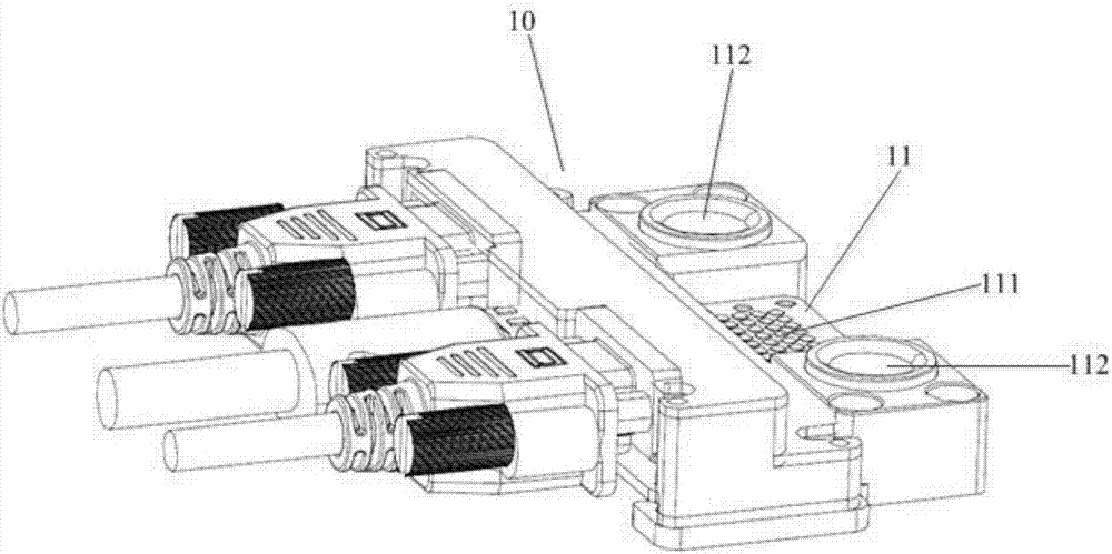
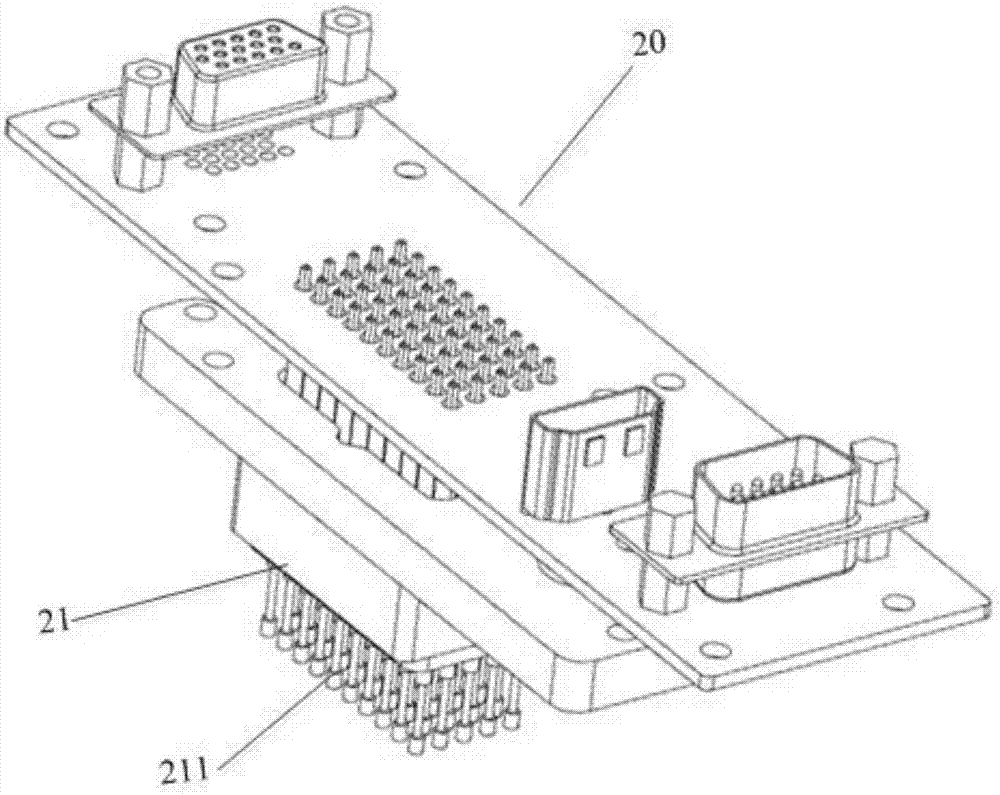
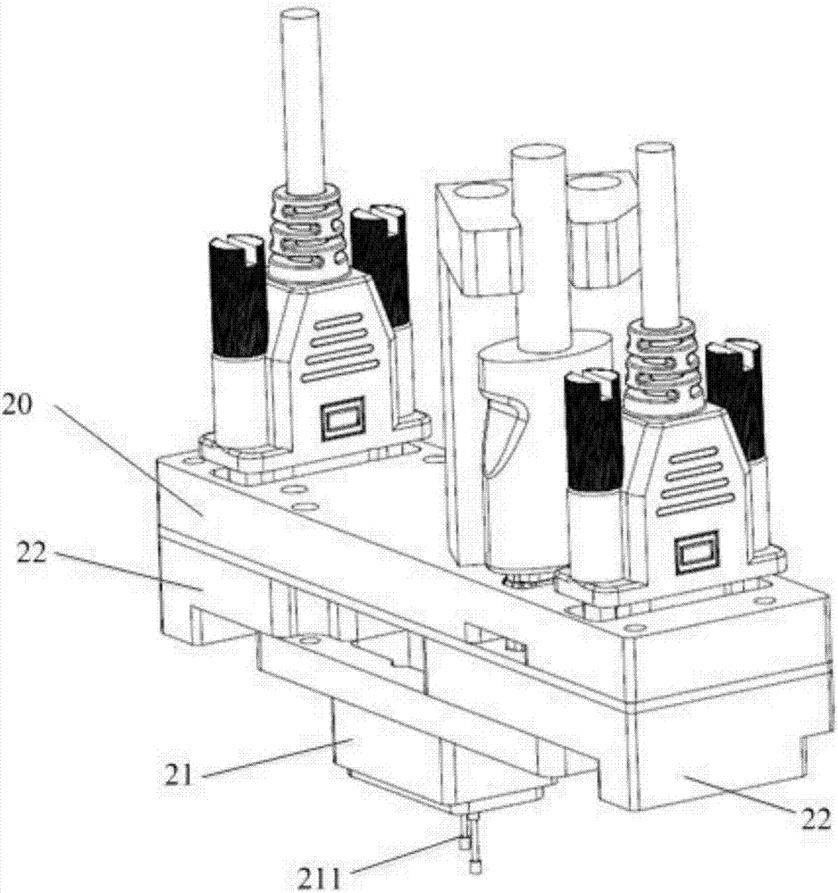
[0041] The embodiment of the present invention provides a kind of automatic plugging and unplugging test device 1, refer to Figure 1-Figure 6 As shown, the device includes a first substrate assembly 10, a second substrate assembly 20 and a direction adjustment assembly 30, and the direction adjustment assembly 30 is connected to the second substrate assembly 20;

[0042] The first substrate assembly 10 is electrically connected to the device to be tested, and a probe pad 11 is arranged on the first substrate assembly 10;

[0043] The second substrate assembly 20 is electrically connected to the test terminal equipment, and a probe base 21 is arranged on the second substrate assembly 20;

[0044] The probe pad 11 is provided with a plurality of contacts 111 for transmitting test signals, and the probe base 21 is provided with a plurality of probes 211 corresponding to the contacts, and the probes 211 transmit test signals by contacting the contacts 111; wherein, First Substra...


PUM


Abstract

The invention discloses an automatic plug wire testing device, and belongs to the field of testing equipment. The automatic plug wire testing device comprises a first substrate assembly, a second substrate assembly and a direction adjustment assembly, and is characterized in that the direction adjustment assembly is connected with the second substrate assembly; the first substrate assembly is electrically connected with a device at the end to be tested, and the first substrate assembly is provided with a probe welding pad; the second substrate assembly is electrically connected with a device at the test end, and the second substrate assembly is provided with a probe base; the probe welding pad is provided with a plurality of contacts, and the product base is provided with a plurality of corresponding probes; and the direction adjustment assembly adjusts the probes on the probe base to be aligned with the contacts on the probe welding pad in the process that the probes are contacted with the contacts. Alignment of the probes on the probe base and the contacts on the probe welding pad is adjusted by the direction adjustment assembly in the testing process through connection between the direction adjustment assembly and the second substrate assembly, so that automatic alignment adjustment is realized, alignment adjustment is not required to be performed manually, and the test efficiency and effect are improved.

Description

technical field [0001] The invention relates to the field of test equipment, in particular to an automatic plug-in and pull-out test device. Background technique [0002] In the process of testing the projector signal, the test equipment is connected to the equipment under test, and the test signal is generally transmitted through the contact of the probe on the test equipment and the contact on the corresponding probe pad, so in order to achieve signal stability and Accuracy, the probe needs to be accurately aligned with the contact position on the probe pad during the test. [0003] In the prior art, the probes are manually aligned with the contacts on the probe pads. However, through the existing technology, due to the small contact area between the probe and the contact, if the contact is inaccurate or the displacement is deviated, the signal transmission will be poor, and the existing technology relies on manual insertion for alignment, which cannot The automation of ...

Claims


Application Information

Patent Timeline
Patent Type & Authority Applications(China)
IPC IPC(8): G01R1/073
CPCG01R1/073
Inventor 余武刘龙席伟
Owner QISDA SUZHOU
Why Eureka
Eureka Blog
Learn More