
Patsnap Eureka
For R&D, Patsnap Eureka makes reading and utilizing patents & technical documents easy.
Patsnap Eureka AIR
Designed for self-driven R&D workflows. Generate viable solutions, solve complex R&D challenges, empower your innovation with AI.

Patsnap Eureka Materials
Designed for material experts only. Revolutionize your material R&D, from search, analyze, to developing new materials.

TechResearch
Generate reliable direction feasibility study reports for your R&D in just a few steps.

TechSeek
Discover and master advanced knowledge NOW. Basics, ideas, possibilities, all at once.

TechMind
As an expert in R&D Theories, TechMind can generates customized viable solutions instantly.

TechRisk
Analyze your overall solution with one click, know your potential R&D risks in advance.

TechMonitor
Get weekly tech updates, stay abreast of the latest tech innovations and key insights.
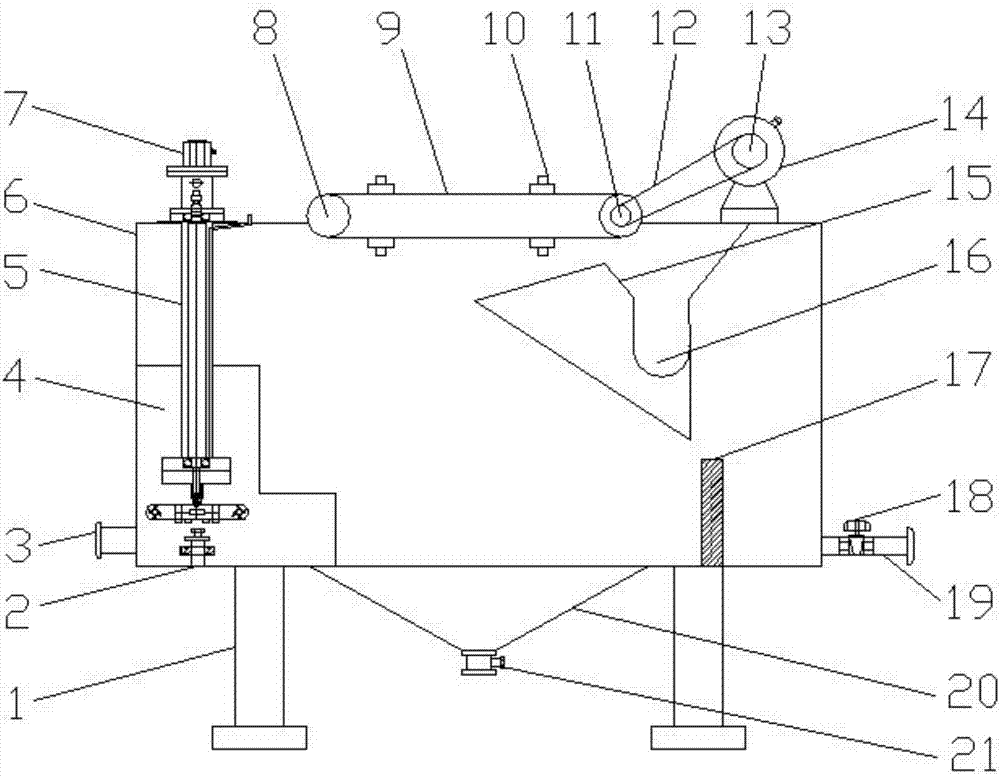
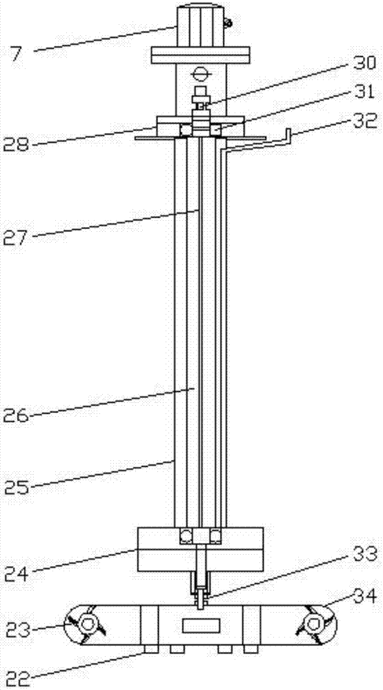
Cavitation air flotation machine used for sewage treatment and being able to segment bubbles
A technology of sewage treatment and air flotation machine, which is applied in the direction of water/sewage treatment, flotation water/sewage treatment, water/sewage treatment equipment, etc. It can solve the problems of severe wear, short life, short retention time in water, and inability to add lubricating oil, etc. problems, to achieve the effects of good mechanical performance, long retention time, automatic treatment of particle sediment and high work efficiency
- Summary
- Abstract
- Description
- Claims
- Application Information
AI Technical Summary
Problems solved by technology
Method used
Image


Examples
Embodiment Construction
[0022] The following will clearly and completely describe the technical solutions in the embodiments of the present invention with reference to the accompanying drawings in the embodiments of the present invention. Obviously, the described embodiments are only some, not all, embodiments of the present invention. Based on the embodiments of the present invention, all other embodiments obtained by persons of ordinary skill in the art without making creative efforts belong to the protection scope of the present invention.
[0023] see Figure 1-5 , an embodiment provided by the present invention: a concave vortex air flotation machine for sewage treatment with separable bubbles, including an ultrasonic generator 2, an aeration device 5, a box body 6, a second motor 14, a hollow pipe 26 and a diffuser Gas impeller 34, a conical sludge collection tank 20 is provided at the central position of the bottom of the box body 6, and a sewage valve 21 is installed at the bottom of the slud...
PUM
 Abstract
Description
Claims
Application Information
 - R&D Engineer
- R&D Manager
- IP Professional
- Industry Leading Data Capabilities
- Powerful AI technology
- Patent DNA Extraction
Browse by: Latest US Patents, China's latest patents, Technical Efficacy Thesaurus, Application Domain, Technology Topic, Popular Technical Reports.
© 2024 PatSnap. All rights reserved.Legal|Privacy policy|Modern Slavery Act Transparency Statement|Sitemap|About US| Contact US: help@patsnap.com