An integrated circulating fluidized bed equipment

A circulating fluidized bed and equipment technology, which is applied in the fields of gas-solid heat exchange, gas-solid phase catalytic reaction, and solid combustion reaction, can solve the problems of high equipment cost and operating cost, small operating flexibility, and complicated equipment, and reduce production and design cost, avoiding dead zone, and simplifying the effect of production equipment

Active Publication Date: 2019-12-13
TIANJIN UNIV
View PDF7 Cites 0 Cited by
  • Summary
  • Abstract
  • Description
  • Claims
  • Application Information

AI Technical Summary

Problems solved by technology

[0006] The invention proposes an integrated circulating fluidized bed, which integrates the fluidized bed, gas-solid separator, gas-solid conveying and circulation system, and solves the problems of complex equipment, high energy consumption, equipment cost and operation of traditional circulating fluidized bed Disadvantages such as high cost and low operating flexibility can not only realize solid phase fluidization and plug flow flow form, avoid gas short circuit, but also complete gas-solid separation in time, and realize internal circulation of solid phase, and more importantly, integration The fluidized bed has good continuity, uniformity and adaptability

Method used


Image

  • An integrated circulating fluidized bed equipment
  • An integrated circulating fluidized bed equipment

Examples


Embodiment Construction

[0027] The patent of the present invention is further described in conjunction with the accompanying drawings:

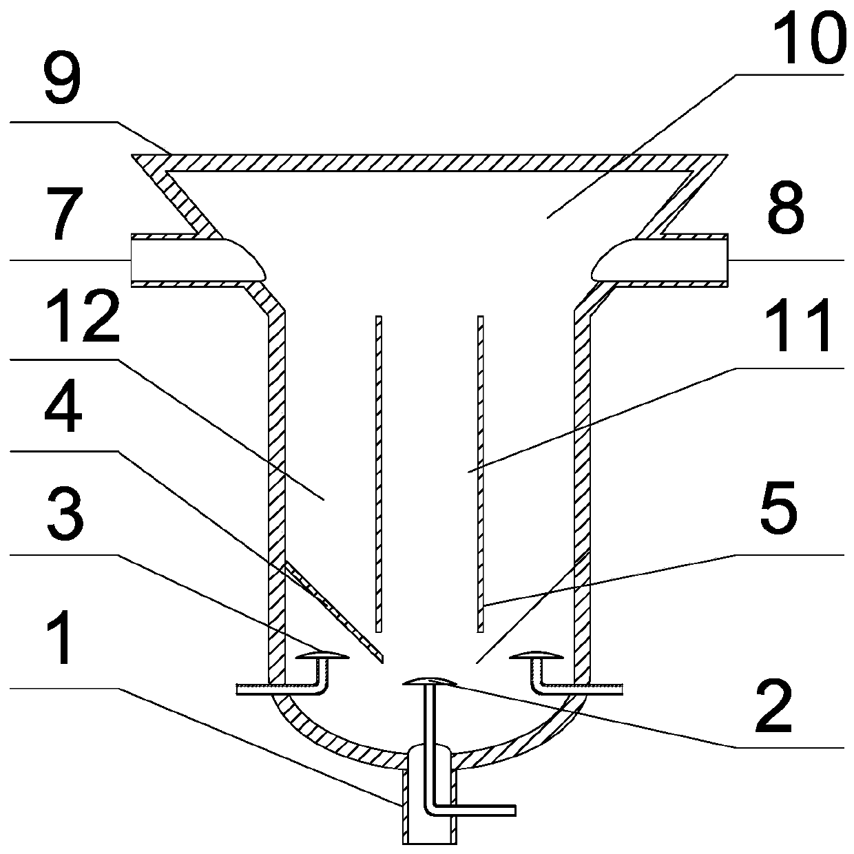
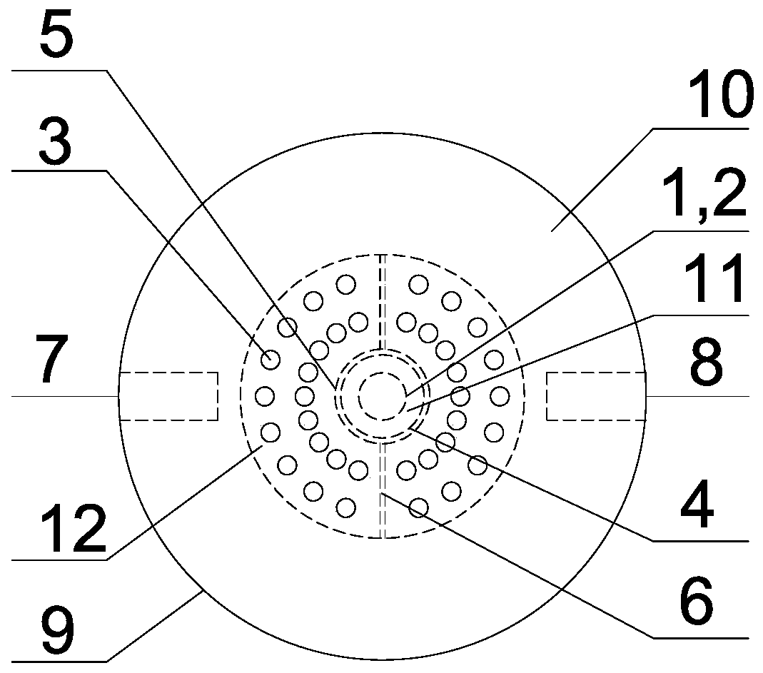
[0028] Such as figure 1 , 2 Shown: an integrated circulating fluidized bed equipment, from bottom to top are solid collection port (1), central gas distributor (2), annular gas distributor (3), solid collector (4), inner Sleeve (5), gas outlet (7), solid inlet (8). The central gas distributor (2) is located directly under the inner sleeve (5), and the annular gas distributor (3) is located around the central gas distributor (2) and between the inner and outer sleeves.

[0029] The upper part of the outer sleeve (9) is a frustum-shaped structure with a thick upper part and a thinner lower part. The ratio of the maximum diameter to the minimum diameter is 2, and the bottom part is an equal-diameter cylinder, which is made by welding with the upper part. The diameter of the inner sleeve (5) accounts for 30% of the diameter of the lower part of the outer sleeve (9), ...


PUM


Abstract

The invention relates to an integrated circulating fluidized bed apparatus. The upper part of an external sleeve cylinder is in a circular truncated cone structure with a thick top and a thin bottom, wherein ratio of maximum diameter to minimum diameter is 1.1-5. The lower part of the external sleeve cylinder is a cylinder in equal diameter and is connected to an internal sleeve cylinder through a screw bolt. The fluidized bed apparatus, from bottom to top, successively includes a solid collection port, a center gas distributor, an annular space gas distributor, a solid collector, and the internal sleeve cylinder. A gas outlet and a solid inlet are disposed on the upper part of the external sleeve cylinder. The center gas distributor is located right under the internal sleeve cylinder and the annular space gas distributor is located around the periphery of the center gas distributor and between the internal and the external sleeve cylinders. A gas-solid separation zone is formed in the upper part of the external sleeve cylinder. The lower part of the external sleeve cylinder is totally cylindrical in shape and is separated into a lifting zone and a circulating zone by means of the internal sleeve cylinder. The apparatus integrates a fluidized bed, a solid circulating system and a gas-solid separation system, so that the production apparatus is simplified. Gas flows in the status of plug flow, so that a gas phase and a solid phase are completely contacted and dead zone is avoided. The apparatus reduces power consumption and reduces manufacturing and producing cost.

Description

technical field [0001] The invention relates to an integrated circulating fluidized bed equipment suitable for the mass transfer and heat transfer process between gas-solid two phases, which can be used in the fields of gas-solid phase catalytic reaction, gas-solid heat exchange, solid combustion reaction and the like. Background technique [0002] Compared with fixed beds, fluidized beds have the characteristics of low pressure drop and high mass and heat transfer efficiency. They are widely used in mass transfer, heat transfer, drying and other technical fields, and are of great significance to industrial and agricultural production. As a special fluidized bed, the circulating fluidized bed can realize the circulation of solid matter into a fluidized state, increase the contact time between solid and gas, improve the efficiency of mass transfer and heat transfer, and is conducive to clean production. Application prospect and research value. [0003] The existing circulati...

Claims


Application Information

Patent Timeline
Patent Type & Authority Patents(China)
IPC IPC(8): B01J8/24F23C10/00F23C10/20
CPCB01J8/007B01J8/24B01J2208/00991F23C10/00F23C10/20
Inventor 刘春江郭凯齐文哲郑龙云李传玺刘辉
Owner TIANJIN UNIV
Why Eureka
Try Eureka