A steam-water separator component exhaust structure specially used for nuclear power plant steam generators

A steam-water separator and steam generator technology, which is applied in separation methods, dispersed particle separation, chemical instruments and methods, etc., can solve the problems of insufficient steam exhaust pipes and insufficient steam exhaust capacity to meet the requirements, and save steam. The space of the cylinder on the generator can meet the demand of exhaust steam and ensure the effect of separation efficiency

Active Publication Date: 2019-05-07
NUCLEAR POWER INSTITUTE OF CHINA
View PDF9 Cites 1 Cited by
  • Summary
  • Abstract
  • Description
  • Claims
  • Application Information

AI Technical Summary

Problems solved by technology

[0004] The technical problem to be solved by the present invention is that the steam exhaust capacity of the small-diameter steam-water separator assembly cannot meet the requirements due to the limited space on the upper cylinder of the steam generator, and the steam exhaust capacity cannot meet the requirements. The exhaust structure of the steam-water separator assembly of the steam generator, the exhaust structure increases the steam circulation area of ​​the steam-water separator exhaust structure under the condition that the diameter of the upper cylinder of the steam generator remains unchanged, and ensures the exhaust of the steam-water separator exhaust structure. steam capacity to meet the steam exhaust requirements of small-diameter steam-water separator components, avoiding the hedge between steam in the steam-water mixture and the tangential drainage of the steam-water separator, thereby ensuring the separation efficiency of the steam-water separator and the dryer, and obtaining qualified dry saturated steam

Method used


Image

  • A steam-water separator component exhaust structure specially used for nuclear power plant steam generators
  • A steam-water separator component exhaust structure specially used for nuclear power plant steam generators
  • A steam-water separator component exhaust structure specially used for nuclear power plant steam generators

Examples


Embodiment 2

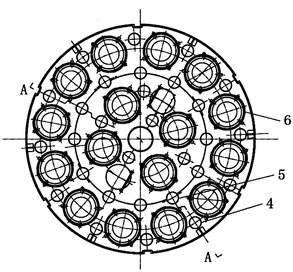
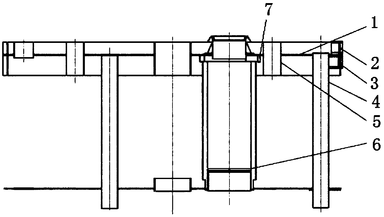
[0023] This embodiment is used to solve the hydrophobic problem. attached figure 1 And attached figure 2 It is a gravity-separated hydrophobic structure widely used in steam generators of existing nuclear power plants, and it mainly includes an upper deck 1 , an upper water-retaining coaming 2 , a lower water-retaining coaming 3 , a drain pipe 4 and an exhaust pipe 5 . The water collecting pan is formed around the upper water retaining coaming 2 and the upper deck 1 to collect the large-sized water droplets from the outlet of the steam-water separator and fall after being separated by gravity, and then flow into the water space of the upper cylinder of the steam generator through the drain pipe 4 , the function of the lower water retaining board 3 is to block the water flowing out from the steam-water separator, and act as a guide to make the water flow down gently along the water retaining board under the action of gravity. The steam also acts as a guide, so that the steam...


PUM


Abstract

The invention discloses a steam-water separator component exhaust structure specially used for steam generators in nuclear power plants. The steam-water separators are combined to form several concentric ring structures with different diameters, and the adjacent steam-water separation in each ring structure There are exhaust steam passages between the devices, and the exhaust steam passages pass through the upper deck. This invention increases the steam circulation area of ​​the exhaust structure of the steam-water separator under the condition that the diameter of the upper cylinder of the steam generator remains unchanged, saves the space of the upper cylinder of the steam generator, ensures the exhaust capacity of the exhaust structure of the steam-water separator, and satisfies The steam exhaust requirements of small-diameter steam-water separator components create conditions for the application of compact and efficient small-diameter steam-water separators, and avoid the steam in the steam-water mixture from being opposed to the tangential drainage of the steam-water separator, thereby ensuring that the steam-water separator and even the dryer The separation efficiency is high, and dry saturated steam with qualified quality is obtained.

Description

technical field [0001] The invention relates to nuclear power plant steam generator technology, in particular to the application of a compact, high-efficiency and small-diameter steam-water separator, and in particular to a steam-exhaust structure of a steam-water separator assembly specially used in a nuclear power plant steam generator. Background technique [0002] The steam-water separator is located under the dryer and the gravity separation space in the steam generator of the nuclear power plant. Its function is to roughly separate the steam-water mixture, reduce the humidity at the inlet of the dryer, and ensure that the dryer supplies qualified dry saturated steam to the steam turbine, ensuring that the steam turbine safe and economical operation. [0003] The steam-water mixture coming out of the tangential drain (or porous drain) of the steam-water separator is mainly composed of water, but also contains a small amount of steam. Appropriate exhaust structures shoul...

Claims


Application Information

Patent Timeline
Patent Type & Authority Patents(China)
IPC IPC(8): B01D53/26
CPCB01D53/26
Inventor 陈军亮张富源黄伟任云何戈宁谈国伟汤臣杭吴杨
Owner NUCLEAR POWER INSTITUTE OF CHINA
Why Eureka
Try Eureka