Cleaning head and cleaning tool using cleaning head

A technology for cleaning tools and cleaning heads, which is applied in the field of cleaning heads, can solve problems such as poor cleaning effect of stubborn stains, achieve the effect of reducing the number of replacement cleaning heads and improving cleaning efficiency

Inactive Publication Date: 2017-07-04
阳珉
View PDF1 Cites 5 Cited by
  • Summary
  • Abstract
  • Description
  • Claims
  • Application Information

AI Technical Summary

Problems solved by technology

[0007] The beneficial effects of the present invention mainly lie in that during the rotation of the cleaning head, the cleaning blades bent towards the direction of rotation can gradually gather the dirt and limit it to the middle position below the cleaning head, preventing the dirt from being thrown away by the rotating cleaning head; at the same time The lower edge of the cleaning blade facing the direction of rotation has a certain scraping effect on the surface to be cleaned, which can overcome the shortcomings of ordinary rotary cleaning heads that can only be wiped with the bottom plane, and the cleaning effect on stubborn stains is not good, and when the cleaning head itself is dirty , still has a certain cleaning ability, which can reduce the number of times to replace the cleaning head and improve cleaning efficiency

Method used


Image

  • Cleaning head and cleaning tool using cleaning head
  • Cleaning head and cleaning tool using cleaning head
  • Cleaning head and cleaning tool using cleaning head

Examples


Embodiment 1

[0027] Embodiment 1: as figure 1 , figure 2 As shown, the cleaning head is an impeller structure, including two circumferentially distributed cleaning blades 11 for wiping the surface to be cleaned. In this embodiment, the rotation direction of the cleaning head is figure 1 As shown by middle arrow A, the cleaning blade 11 is bent toward the rotation direction of the cleaning head; the cleaning head also includes an upper cover 13, the cleaning blade 11 is arranged under the upper cover 13, and the center of the upper cover 13 is provided with a The through hole 14 of the channel; in the present embodiment, the material of the cleaning blade and the upper cover is a flexible water-absorbing wiping material, preferably an integrally formed polyvinyl alcohol collodion material, suitable for wet mopping, and can be used to clean the ground, glass, etc. Surface, and has good water absorption;

[0028] In the present invention, the impeller structure should not be understood as ...

Embodiment 2

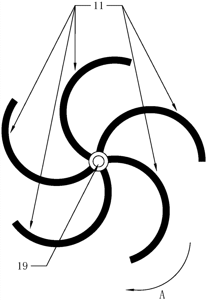
[0029] Embodiment 2: as image 3 As shown, the cleaning head is an impeller structure, including a plurality of cleaning blades 11 distributed circumferentially around the central axis 19 for wiping the surface to be cleaned; the rotation direction of the cleaning head is image 3 Shown in the middle arrow A, the cleaning blade 11 is bent toward the rotation direction of the cleaning head; the cleaning blade 11 is made of a brush bundle, and the brush bundle can be natural or artificial bristles. In order to keep the shape of the brush bundle better, also Elastic steel wires or elastic plastic strips for shaping can be arranged in the brush bundle; the cleaning head in this embodiment is mainly used as a hand-push sweeper or a sweeper robot.

Embodiment 3

[0030] Embodiment 3: as Figure 4 , Figure 5 As shown, the cleaning head is an impeller structure, which is composed of a scrub brush form, including a plastic upper cover 13, located below the upper cover, a plurality of circumferentially distributed cleaning blades 11 composed of bristles, and a central axis of the upper cover The position is provided with the through hole 14 that is used as installation location or dust suction channel; In the present embodiment, the rotation direction of cleaning head is Figure 4 As shown by the middle arrow A, the cleaning blade 11 is bent toward the rotation direction of the cleaning head; the cleaning head in this embodiment can be used for a sweeping car, a hand-push sweeping machine or a sweeping robot.


PUM


Abstract

The invention discloses a cleaning head for a rotary cleaning tool. The cleaning head is of an impeller structure and comprises multiple cleaning blades which are distributed in the peripheral direction and used for cleaning a surface to be cleaned, wherein the cleaning blades are bent towards the rotating direction of the cleaning head during working; and channels allowing dirt to move therein are formed between every two adjacent cleaning blades, the cleaning blades bent towards the rotating direction enable dirt to make centred motion along the rotating side of the cleaning blades when the cleaning head rotates, and a dirt gathering function is realized. By the adoption of the cleaning head, the defect of ordinary rotary cleaning tools that dirt can not be gathered and is thrown away easily can be overcome effectively, so that cleaning efficiency is improved. The cleaning head can be applied to cleaning tools like a sweeper, a floor mopping machine, an electric rotary mop, a sweeping robot and an electric window cleaner.

Description

technical field [0001] The invention relates to the field of cleaning tools, in particular to a cleaning head for rotary cleaning tools such as sweepers, floor moppers, electric rotary mops, floor sweeping robots, and electric window cleaners. Background technique [0002] In the prior art, tools that use the cleaning head rotation method to clean have been widely used, such as sweepers, floor moppers, electric rotary mops, floor sweeping robots, electric window cleaners, etc., the cleaning head generally adopts a disc brush, a circular Shaped mop, or side brush and other structures. [0003] Taking the common electric rotary mop as an example, its cleaning head usually uses one or two round mops, which are rotated by a motor installed in the body to wipe the ground. The way to clean, can't gather the dirt together like ordinary mop, so the mop is very easy to get dirty, drag a small piece of ground, you have to take off the mop for replacement and cleaning, even more times...

Claims


Application Information

Patent Timeline
Patent Type & Authority Applications(China)
IPC IPC(8): A47L11/16A47L11/164A47L11/206A47L11/24A47L11/40
CPCA47L11/24A47L11/40A47L11/4038A47L11/4094
Inventor 阳珉
Owner 阳珉
Why Eureka
Try Eureka