Automatic cow back-off device having rotating disk system
An automatic, turntable technology, applied in milking devices, dairy products, applications, etc., can solve the problems of cows and manual driving of cows, which consumes manpower and material resources, and the effect of returning cows is not good.
- Summary
- Abstract
- Description
- Claims
- Application Information
AI Technical Summary
Problems solved by technology
Method used
Image

Examples
Embodiment 1
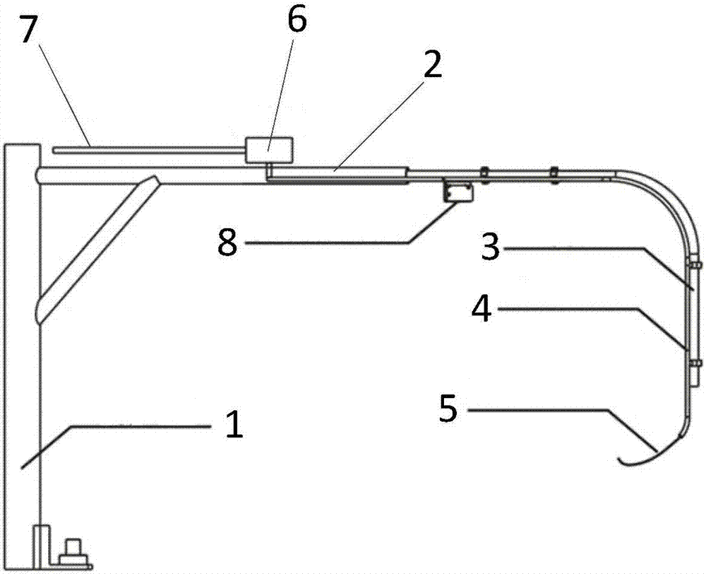
[0074] Such as figure 1 As shown, this embodiment provides an automatic cattle removal device with a turntable system, including: an automatic cattle removal device.
[0075] The automatic cow removal device includes: a support column 1 , a casing 2 , a support arm 3 , a compressed air pipe 4 , a cow removal air pipe 5 , a solenoid valve 6 , an air source device 7 and a photoelectric detector 8 .
[0076] The casing 2 is laterally and fixedly connected to the support column 1; one end of the support arm 3 is sleeved inside the casing 2, and the other end is located outside the casing 2; the solenoid valve 6 is located on the casing 2 above and connected to the sleeve 2; one end of the compressed air pipe 4 is connected to the solenoid valve 6 through the sleeve 2, and the other end is located outside the sleeve 2.
[0077] The solenoid valve 6 is provided with a first through hole and a second through hole, wherein the air source device 7 is connected to the solenoid valve 6 ...
Embodiment 2
[0083] The present embodiment provides a kind of automatic cattle withdrawal device with the turntable system, the device in the present embodiment is similar to the device in the embodiment 1, the difference is:
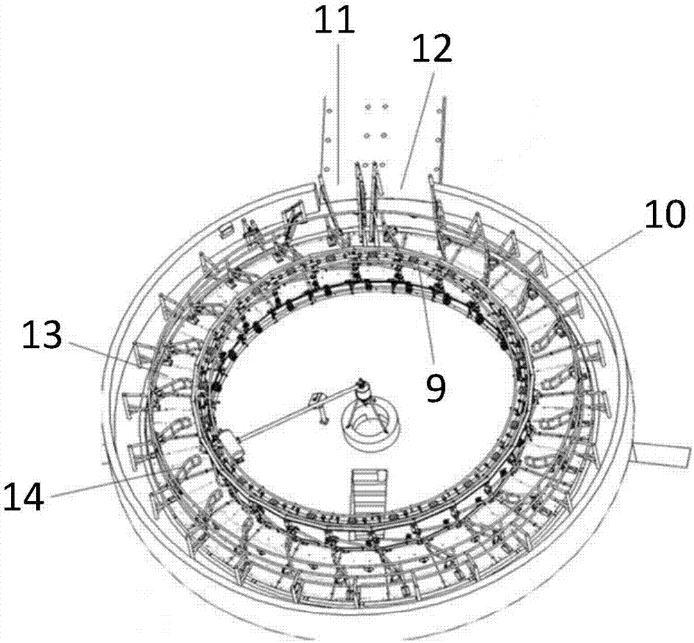
[0084] Such as figure 2 As shown, in this embodiment, the herringbone turntable is a circular groove, and the herringbone turntable is provided with an inner ring 9 and an outer ring 10;
[0085] The outer ring 10 is provided with an inlet 11 and an outlet 12;
[0086] The herringbone turntable is provided with 24 station areas 13;
[0087] The outer ring 10 is provided with a guide rod 14 corresponding to the station area 13, one end of the guide rod 14 is connected to the outer ring 10, and the other end is placed in the station area 13, and The guide rod 14 is placed obliquely;
[0088] A sliding device is provided at the joint between the guide rod 14 and the outer ring 10 for sliding along the outer ring 10;
[0089] The outer ring 10 is provided with a tr...
Embodiment 3
[0091] The present embodiment provides a kind of automatic cattle withdrawal device with the turntable system, the device in the present embodiment is similar to the device in the embodiment 1, the difference is:
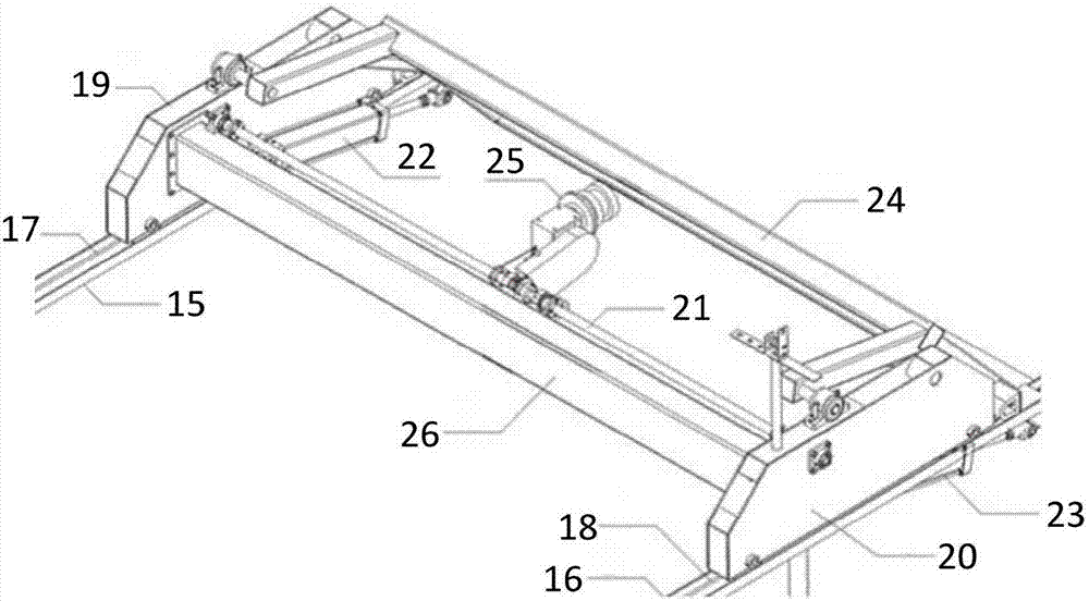
[0092] Such as image 3 As shown, in the present embodiment, described automatic cattle herding equipment comprises: left track 15, right track 16, left chain 17, right chain 18, left board box 19, right side board box 20, transmission shaft 21, left cylinder 22. Right cylinder 23 and flip door 24;
[0093] The left track 15 and the right track 16 are placed on both sides of the waiting area;
[0094] Described left track 15 is provided with described left chain 17, and described right track 16 is provided with described right chain 18;
[0095] The left chain 17 passes through the left board box 19, and the right chain 18 passes through the right side board box 20;
[0096] The gears at both ends of the transmission shaft 21 are respectively connected with the l...
PUM
 Abstract
Description
Claims
Application Information
 - R&D
- Intellectual Property
- Life Sciences
- Materials
- Tech Scout
- Unparalleled Data Quality
- Higher Quality Content
- 60% Fewer Hallucinations
Browse by: Latest US Patents, China's latest patents, Technical Efficacy Thesaurus, Application Domain, Technology Topic, Popular Technical Reports.
© 2025 PatSnap. All rights reserved.Legal|Privacy policy|Modern Slavery Act Transparency Statement|Sitemap|About US| Contact US: help@patsnap.com