
Method for reducing influence of temperature change on optical fiber sensor measurement signal

A fiber optic sensor, temperature change technology, applied in the direction of mitigating undesired effects, etc., can solve the problems of low measurement accuracy and ineffective measurement, achieve the effect of wide application, improve attenuation loss, and solve the problem of temperature cross-sensitivity

Active Publication Date: 2017-06-30
NANJING UNIV OF AERONAUTICS & ASTRONAUTICS
View PDF7 Cites 2 Cited by
  • Summary
  • Abstract
  • Description
  • Claims
  • Application Information

AI Technical Summary

Problems solved by technology

[0006] The purpose of the present invention is to propose a method for reducing the influence of temperature changes on the measurement signal of an optical fiber sensor, aiming at the problem that the current optical fiber sensor is affected by the cross influence of temperature during the measurement process, which makes the measurement accuracy low or the measurement is invalid

Method used

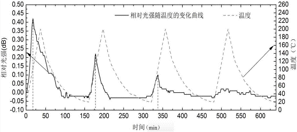
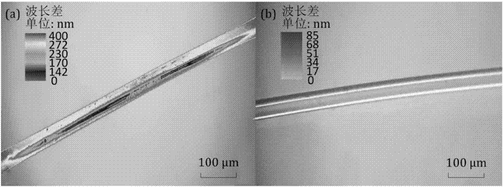

Image

  • Method for reducing influence of temperature change on optical fiber sensor measurement signal
  • Method for reducing influence of temperature change on optical fiber sensor measurement signal
  • Method for reducing influence of temperature change on optical fiber sensor measurement signal

Examples


example 1

[0031] The tapered optical fiber sensor in this example is made by longitudinal melting and stretching of optical fiber. This process will generate a large amount of residual stress in the optical fiber tapered region, making this type of sensor extremely sensitive to temperature. The specific implementation method of the present invention will be described below in conjunction with the accompanying drawings and the reduction of the influence of temperature changes on the measurement signal of the tapered optical fiber sensor as an example, and the present invention is not limited to this embodiment. Concrete steps of the present invention include:

example 1

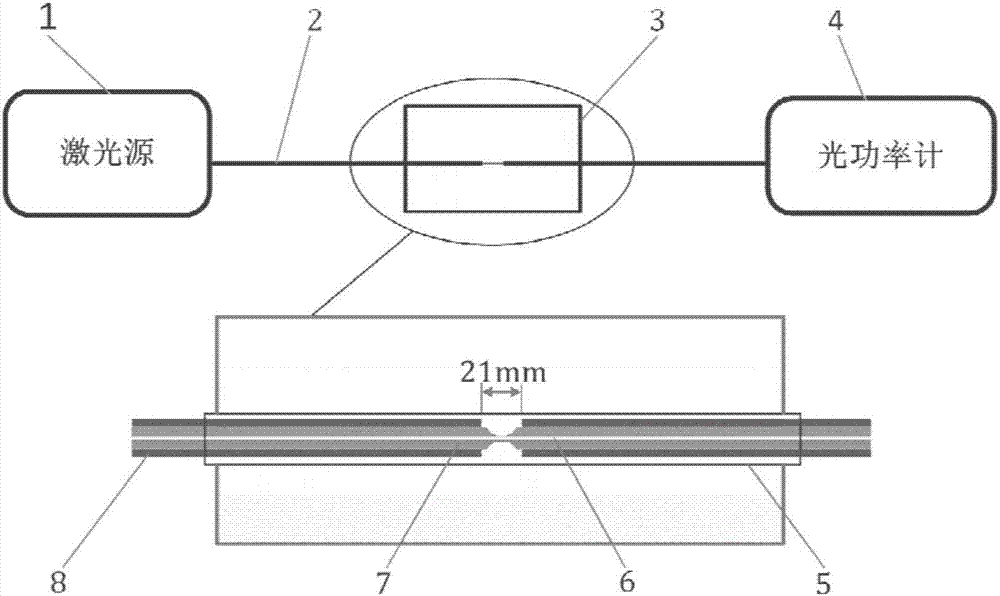
[0033] 1. Cut the single-mode silica fiber 2 (Corning single-mode fiber) 1.5m, and put a 0.3mm diameter quartz capillary into the fiber 2. Then use an optical fiber cutter to cut flat the end faces of the two optical fibers 2, and weld standard connectors on the end faces of the two optical fibers. In order to monitor the tapering process of the optical fiber 2, a 1550 nm laser source 1 is connected to one end of the optical fiber 2 through a standard connector, and an optical power meter 4 is connected to the other end, such as figure 1 shown in the upper part.

[0034] 2. Remove the 1.5cm-long optical fiber coating layer 8 from the middle part of the optical fiber, and clean the area with alcohol. Then it is clamped on the optical fiber tapering instrument for tapering. Set the tapering speed to 0.5 mm / s, the flame temperature to 1000 °C, and the diameter of the cone to 35 μm. Check the change of the light intensity of the optical power meter 4 after tapering to judge the...

example 2

[0041] The difference between this example and Example 1 is that multiple optical fiber sensors are processed at the same time, but when processing multiple optical fiber sensors at the same time, it is necessary to ensure that the maximum temperature difference between adjacent optical fibers is less than 20 degrees Celsius, and the rest is the same as the above Example 1.


PUM

PropertyMeasurementUnit
Glass transition temperatureaaaaaaaaaa
Diameteraaaaaaaaaa

Abstract

The invention provides a method for reducing the influence of the temperature change on an optical fiber sensor measurement signal, and aims at meeting the use requirements of an optical fiber sensor in the varying temperature environment. According to the method, circulating heating and cooling are performed on an optical fiber sensing area so that the residual stress of the optical fiber sensing area can be substantially reduced, and the sensor is enabled not to be interfered or influenced by the temperature basically. The method has the characteristics of being simple and practicable and low in cost so as to have wide market value and application prospect in the technical field of optical fiber sensing and monitoring.

Description

technical field [0001] The invention relates to the technical field of optical fiber sensing and monitoring, in particular to a method for reducing the influence of temperature changes on the measurement signal of an optical fiber sensor. Background technique [0002] Optical fiber sensors have the advantages of extremely high sensitivity and precision, anti-electromagnetic interference, high dielectric strength, corrosion resistance, integration of sensing and transmission, and compatibility with digital communication systems, and have been widely used in the field of sensing and monitoring. During the manufacture and use of the sensor, a large amount of residual stress will inevitably be generated in the sensing area, which will cause a large amount of stress birefringence in the optical fiber sensing area, causing the measured physical signal to drift with time. When the temperature changes, the distribution of internal stress in the sensing area also changes with the tem...

Claims


Application Information

Patent Timeline
IPC IPC(8): G01D3/028
CPCG01D3/028
Inventor 李迎光何永喜
Owner NANJING UNIV OF AERONAUTICS & ASTRONAUTICS
Learn More