
Ship-to-ship transfer system based on shore-based liquefied natural gas receiving station

A technology for liquefied natural gas and receiving stations, applied in pipeline systems, liquid distribution, transportation or transfer devices, transportation and packaging, etc., can solve problems such as poor transfer speed and timeliness of transfer, power consumption of in-tank pumps, trade disputes, etc. Improve transport efficiency and save energy

Active Publication Date: 2017-06-30
CHINA HUANQIU CONTRACTING & ENG CO LTD
View PDF7 Cites 9 Cited by
  • Summary
  • Abstract
  • Description
  • Claims
  • Application Information

AI Technical Summary

Problems solved by technology

[0008] (1) The transshipment capacity depends on the storage tank capacity of the receiving station, that is, the receiving station with a small storage capacity or the receiving station cannot meet the transshipment requirements of large loading ships when the demand for external transportation of the pipeline network is large;
[0009] (2) The transfer speed and timeliness of transfer are poor, that is, the loading speed is limited by the maximum loading capacity of the tank pump at the receiving station, and the loading operation can only be carried out after 10-12 hours of unloading operation;
[0010] (3) The energy consumption of the receiving station during the transfer process is relatively high, that is, the pump in the tank has a considerable degree of power consumption during the transfer process, and there are two flashes of LNG when it enters the storage tank of the receiving station and the loading ship during each transfer process. The amount of surplus volatile gas that needs to be processed by the receiving station in the secondary flashing process is much higher than that of ship-to-ship direct transfer;
[0011] (4) It is difficult to meet the third party who has strict requirements on the quality of the incoming ship's gas during transshipment, and trade disputes are prone to occur during the transshipment process, that is, the mixing of unloading gas and storage gas in the storage link will cause liquefied natural gas components and calorific value, etc. Great changes in quality

Method used


Image

  • Ship-to-ship transfer system based on shore-based liquefied natural gas receiving station
  • Ship-to-ship transfer system based on shore-based liquefied natural gas receiving station
  • Ship-to-ship transfer system based on shore-based liquefied natural gas receiving station

Examples


Embodiment Construction

[0035] The following will clearly and completely describe the technical solutions in the embodiments of the present invention with reference to the accompanying drawings in the embodiments of the present invention. Obviously, the described embodiments are only some, not all, embodiments of the present invention. Based on the embodiments of the present invention, all other embodiments obtained by persons of ordinary skill in the art without making creative efforts belong to the protection scope of the present invention.

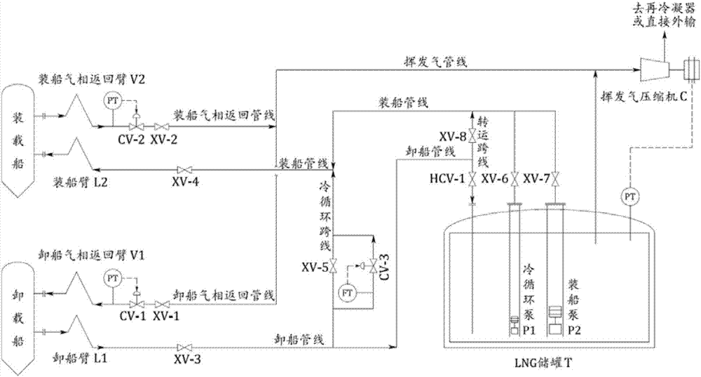
[0036] figure 1 The structural diagram of the ship-to-ship transfer system based on the shore-based LNG receiving station provided by the present invention, as shown in the figure, the ship-to-ship transfer system based on the shore-based LNG receiving station provided by the present invention includes: the unloading arm L1 , Ship unloading gas-phase return arm V1, ship-loading arm L2, ship-loading gas-phase return arm V2, LNG storage tank T, cold cycle pump P...


PUM


Abstract

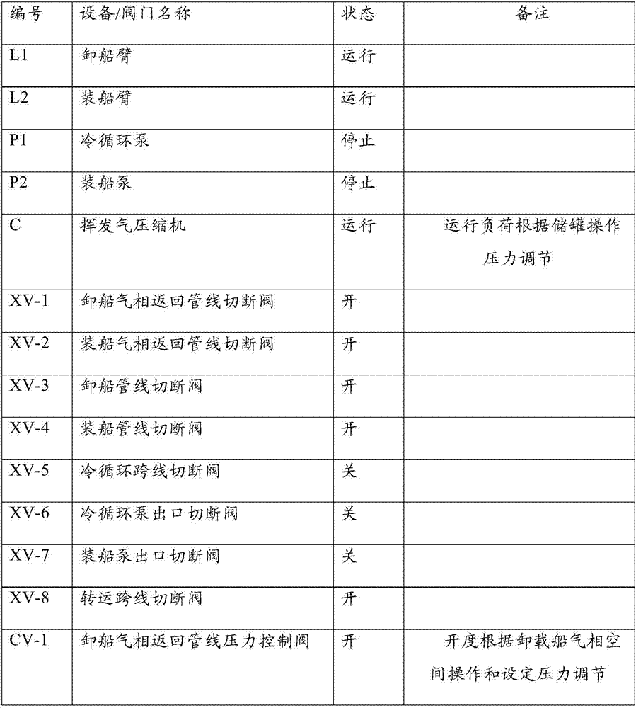
Disclosed is a ship-to-ship transfer system based on a shore-based liquefied natural gas receiving station. The ship-to-ship transfer system based on the shore-based liquefied natural gas receiving station comprises a ship unloading arm L1, a ship unloading gaseous-phase return arm V1, a ship loading arm L2, a ship loading gaseous-phase return arm V2, an LNG storage tank T, a cold circulating pump P1, a ship loading pump P2, a volatile gas compressor C, a ship loading pipeline, a ship unloading pipeline, a volatile gas pipeline, a ship unloading gaseous-phase return pipeline, a ship loading gaseous-phase return pipeline, a cold circulating crossing line and a transfer crossing line. A ship unloading pipeline stop valve XV-3 is arranged on the ship unloading pipeline, and a ship loading pipeline stop valve XV-4 is arranged on the ship loading pipeline. A ship unloading gaseous-phase return pipeline stop valve XV-1 and a ship unloading gaseous-phase return pipeline pressure control valve CV-1 are arranged on the ship unloading gaseous-phase return pipeline. A ship loading gaseous-phase return pipeline stop valve XV-2 and a ship loading gaseous-phase return pipeline pressure control valve CV-2 are arranged on the ship loading gaseous-phase return pipeline. A cold circulating crossing line stop valve XV-5 is arranged on the cold circulating crossing line. A cold circulating pump outlet stop valve XV-6 is arranged in an outlet of the cold circulating pump P1. A ship loading pump outlet stop valve XV-7 is arranged in an outlet of the ship loading pump P2.

Description

technical field [0001] The invention relates to the field of unloading, storage and gasification of liquefied natural gas, in particular to a ship-to-ship transfer system based on a shore-based liquefied natural gas receiving station. Background technique [0002] Traditional liquefied natural gas receiving station loading and transshipment mainly adopts "unloading-storage-loading" operation, and the specific process is as follows: [0003] (1) The incoming gas is discharged into the LNG storage tank of the receiving station through the unloading pipeline of the unloading dock; [0004] (2) The incoming ship gas and storage gas are mixed and stored in the storage tank; [0005] (3) The mixed loading gas is loaded and transshipped by the pump in the tank through the loading dock or reversely through the unloading dock. [0006] Among them, the above-mentioned inbound gas, stored gas and onboard gas are referred to as abbreviations, and they actually refer to inbound LNG, st...

Claims


Application Information

Patent Timeline
Patent Type & Authority Applications(China)
IPC IPC(8): F17C7/02F17C5/02F17C13/00F17D1/14F17D3/01B67D9/00
CPCF17C5/02F17C7/02F17C13/00F17D1/082F17D1/14F17D3/01B67D9/00F17C2270/0105F17C2223/0161F17C2221/033F17C2227/0135F17C2225/0161
Inventor 赵月峰白改玲王红安小霞刘以容牛占川杨娜王志会许驰
Owner CHINA HUANQIU CONTRACTING & ENG CO LTD
Learn More