Geometry of an aeraulic circuit for a hand-held vacuum

A vacuum cleaner, hand-held technology, applied in the directions of vacuum cleaners, suction filters, applications, etc., can solve the problems of high noise, load loss, reduced compactness of handheld vacuum cleaners, and undirected discharge of air flow.

Active Publication Date: 2017-06-30
SEB SA
View PDF6 Cites 9 Cited by
  • Summary
  • Abstract
  • Description
  • Claims
  • Application Information

AI Technical Summary

Problems solved by technology

It was observed that the air flow at the exit of the auxiliary discharge duct was very noisy due to its high velocity
These hand-held vacuum cleaners are therefore noisy, which is inconvenient to the user
[0005] A specific structure exists for the auxiliary discharge duct in order to reduce the noise, but said specific structure creates disadvantages such as load losses at the motor or a reduction in the compactness of the hand-held vacuum cleaner, or even a non-directed air flow discharge

Method used


Image

  • Geometry of an aeraulic circuit for a hand-held vacuum
  • Geometry of an aeraulic circuit for a hand-held vacuum
  • Geometry of an aeraulic circuit for a hand-held vacuum

Examples


Embodiment Construction

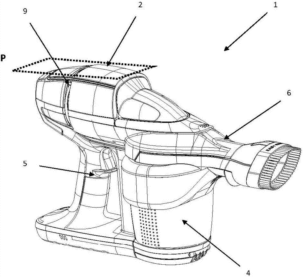
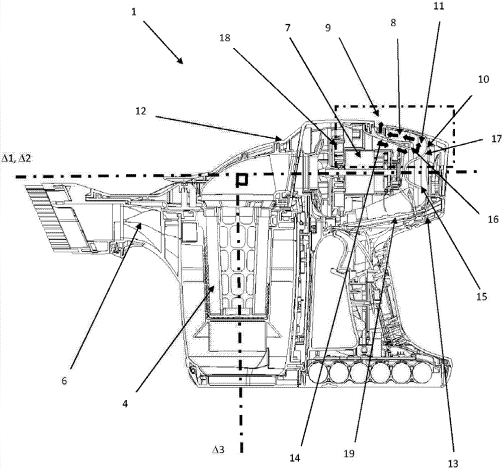
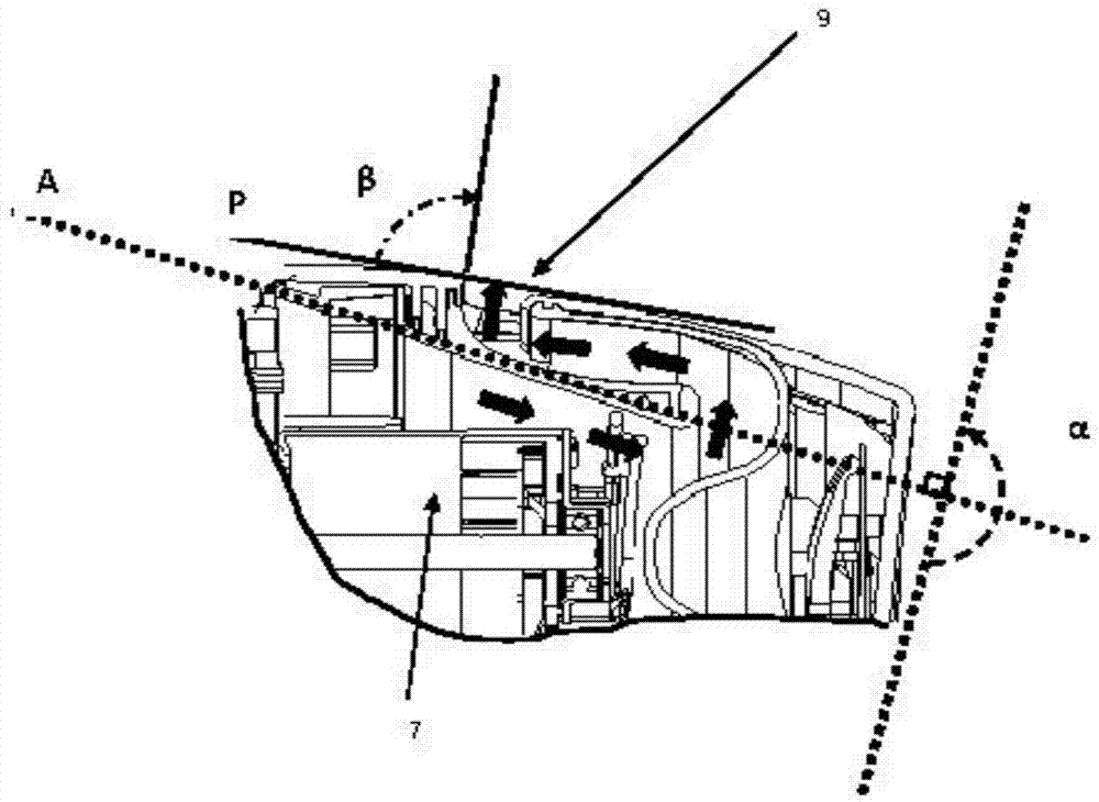
[0034] Such as figure 1 As shown, the handheld vacuum cleaner 1 is composed of a main body 2 . Said body 2 comprises at one of its ends a main suction duct 6 and at its other end an auxiliary exhaust duct 8 . The auxiliary exhaust duct 8 includes an external outlet 9 . Between these two ducts, the body 2 contains a suction mechanism 7 that generates an air flow through the main suction duct 6 and the auxiliary exhaust duct 8 . In other words, air is sucked in through the main suction duct 6 and expelled at the external outlet 9 through the auxiliary exhaust duct 8 . In an implementation variant, sound-insulating foam, not shown, can be provided in the auxiliary exhaust duct 8 in order to further reduce the velocity of the air and thus reduce the noise.

[0035] The handle 5 is fixed on the main body 2 . The grip handle allows the user to operate the handheld vacuum cleaner 1 . In the embodiment of the present invention, the handle 5 is located under the main body 2 for ea...


PUM


Abstract

The invention concerns a hand-held vacuum (1) comprising: a main body comprising a gripping handle and a main air suction conduit (6); a suction means (7) generating a flow of air through the main air suction conduit (6); a cyclonic dust separation device (4) having one or two stages, aeraulically connected to the main suction conduit (6); a secondary air discharge conduit (8) comprising an external outlet (9); characterized in that the secondary air discharge conduit (8) comprises at least one passage (10) in which said secondary conduit (8) forms a bend (11) at an angle of between 120 degrees and 200 degrees and preferably 180 degrees along a trajectory axis (A).

Description

technical field [0001] The present invention relates to a battery-operated hand-held vacuum cleaner of the "bagless" type, using electronically commutated electric motors (MCE) and comprising cyclonic filtering means. [0002] More specifically, the invention relates to the specific structure of the pneumatic circuit for the discharge of the air flow at the outlet of the motor. Background technique [0003] Hand-held vacuum cleaners are known which comprise a main suction duct and a suction mechanism which generates an air flow through the main suction duct. These vacuum cleaners also comprise a cyclonic separation device for dust, which is pneumatically connected to the main suction duct, and an auxiliary discharge duct provided for the discharge air flow. The auxiliary discharge line is usually connected pneumatically to the dust cyclonic separation device and is arranged downstream of the dust cyclonic separation device. [0004] However, the auxiliary discharge duct of...

Claims


Application Information

Patent Timeline
IPC IPC(8): A47L9/00A47L9/16
CPCA47L9/00A47L9/1616A47L5/24A47L9/0081A47L9/16A47L9/1658
Inventor 多纳西安·弗罗费比安·大卫
Owner SEB SA
Why Eureka
Try Eureka