
High-precision multi-phase clock correcting circuit

A multi-phase clock and correction circuit technology, applied in the direction of electrical components, power automatic control, etc., can solve the problems of time mismatch, application environment and temperature influence, and the difference between multi-phase clocks, etc.

Inactive Publication Date: 2017-06-27
UNIV OF ELECTRONICS SCI & TECH OF CHINA
View PDF3 Cites 16 Cited by
  • Summary
  • Abstract
  • Description
  • Claims
  • Application Information

AI Technical Summary

Problems solved by technology

But in reality, due to the influence of non-ideal effects such as delay unit mismatch, transmission path mismatch, temperature change, and chip local stress difference, the difference between multi-phase clocks is unequal, and time mismatch occurs.
[0003] In order to realize a high-precision multi-phase clock, the number of delay units in the delay line can be increased to strengthen the matching between delay units. This method can effectively reduce the phase error and time mismatch, but it increases the circuit scale and system overhead. , and this method depends on the manufacturing level of the process, and is greatly affected by the application environment and temperature

Method used


Image

  • High-precision multi-phase clock correcting circuit
  • High-precision multi-phase clock correcting circuit
  • High-precision multi-phase clock correcting circuit

Examples


Embodiment Construction

[0021] specific implementation plan

[0022] In order to make the object, technical solution and advantages of the present invention clearer, the present invention will be further described in detail below in conjunction with the accompanying drawings and embodiments. It should be understood that the specific embodiments described here are only used to explain the present invention, not to limit the present invention.

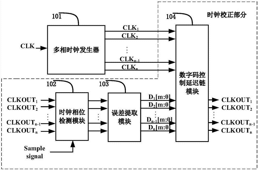
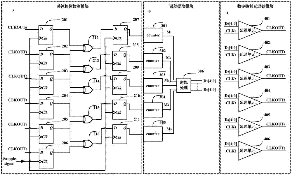
[0023] Aiming at the problems existing in the prior art, the present invention proposes a clock phase correction circuit, which is described here by taking a five-phase clock generator as an example. The multi-phase clock correction module architecture of the present invention is as follows figure 2 As shown, for convenience of description, only the parts related to the embodiment of the present invention are shown.

[0024] In detail, the clock phase correction circuit provided by the embodiment of the present invention includes a multiphase clock generator...


PUM


Abstract

The invention discloses a high-precision multi-phase clock correcting circuit, belonging to the field of analog integrated circuit technology, and particularly relating to a multi-phase clock phase error correction circuit. The high-precision multi-phase clock correcting circuit disclosed by the invention aims to solve the problem that the existing traditional multi-phase clock generator has clock delay errors due to non-ideal effects; a traditional multi-phase clock generation circuit generates a multi-phase clock by using a multi-level delay chain, and errors are caused by the mismatch between the delay units; and the high-precision multi-phase clock correcting circuit is beneficial to reduce the power consumption and save the chip area, is high in clock phase detection precision and easy to implement, is high in adjustment precision of the clock delay units, adopts the code values of digital codes to correspond to the delay size, ensures that the clock accuracy of the clock correction module depends on the feedback adjustment accuracy and the detection accuracy of the clock phase errors, and ensures that the high-precision multi-phase clock can be achieved.

Description

technical field [0001] The invention belongs to the technical field of analog integrated circuits, in particular to a multiphase clock phase error correction circuit. Background technique [0002] The traditional multi-phase clock generator is implemented by a delay-locked loop (Delay-Locked Loop, DLL). By comparing the phases of the reference clock and the feedback clock, the loop is locked, thereby outputting clock signals with multiple equal phases. In theory, the phase The number can be very large, and the phase difference is equal and constant. But in reality, due to the influence of non-ideal effects such as delay unit mismatch, transmission path mismatch, temperature change, and chip local stress difference, the difference between multi-phase clocks is unequal, and time mismatch occurs. [0003] In order to realize a high-precision multi-phase clock, the number of delay units in the delay line can be increased to strengthen the matching between delay units. This meth...

Claims


Application Information

Patent Timeline
Patent Type & Authority Applications(China)
IPC IPC(8): H03L7/081H03L7/18
Inventor 李靖程代州周鹏飞宁宁
Owner UNIV OF ELECTRONICS SCI & TECH OF CHINA
Learn More