Electricity demonstrator with differential amplification
A differential amplification and demonstrator technology, applied in instruments, teaching models, educational appliances, etc., can solve the problems of high cost, insufficient, incomplete experimental instruments, etc., and achieve the effect of simple debugging
- Summary
- Abstract
- Description
- Claims
- Application Information
AI Technical Summary
Problems solved by technology
Method used
Image
Examples
Embodiment Construction
[0106] Specific implementation examples
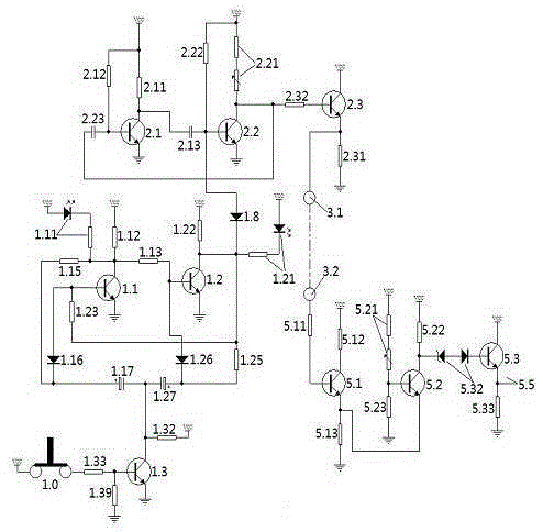
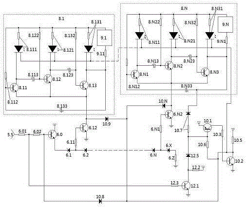
[0107] figure 1 , figure 2 A manner of specific implementation is jointly described.
[0108] 1. Select components: Select the active components according to the figure. 2. The balance voltage regulator tube is composed of a voltage regulator tube and a diode in series. Three switch tubes, two oscillator tubes, isolation tubes, emitter follower tubes, excitation tubes, two differential tubes, balance transistors, and display tubes all use NPN transistors, and 8050 is selected. The terminal P tube is a PNP transistor 8550. The base resistance of the oscillating diode is composed of an adjustable resistor connected in series with a fixed resistor.
[0109] 2. Welding: the multivibrator unit in the electrical demonstrator of differential amplification, the button electronic switch, the electronic circuit of the differential amplification unit such as figure 1 The connection shown, the series voltage divider circuit in the electric...
PUM
 Abstract
Description
Claims
Application Information
 - R&D Engineer
- R&D Manager
- IP Professional
- Industry Leading Data Capabilities
- Powerful AI technology
- Patent DNA Extraction
Browse by: Latest US Patents, China's latest patents, Technical Efficacy Thesaurus, Application Domain, Technology Topic, Popular Technical Reports.
© 2024 PatSnap. All rights reserved.Legal|Privacy policy|Modern Slavery Act Transparency Statement|Sitemap|About US| Contact US: help@patsnap.com


