Electronic expansion valve and valve core thereof

A technology of electronic expansion valve and spool, which is applied to the parts in contact between the valve element and the valve seat, the lifting valve, the valve device, etc., which can solve the problems of failure of the function of adjusting the flow rate, increased noise, and no change in the flow rate. Achieve the effects of increasing the effective flow area, reducing the area of ​​the vortex area, and increasing the mass flow rate

Active Publication Date: 2017-06-23
浙江三花商用制冷有限公司
View PDF8 Cites 9 Cited by
  • Summary
  • Abstract
  • Description
  • Claims
  • Application Information

AI Technical Summary

Problems solved by technology

[0009] When the spool is lifted slowly, the flow rate of the valve body increases gradually, and the flow rate of the refrigerant increases to a certain level, because the head of the spool, that is, the flow adjustment part is of blunt structure, it is easy to form many small vortices at the lower part of the flow adjustment part. , eventually forming turbulence or turbulence, which not only increases the noise, but also tends to cause the flow rate to remain unchanged or decrease, resulting in the failure of the function of regulating the flow rate
[0010] Therefore, how to improve the structure of the spool of the electronic expansion valve to avoid turbulent flow at the bottom of the spool when the flow rate increases, which affects the adjustment of the flow rate, is a technical problem that those skilled in the art need to solve at present.

Method used


Image

  • Electronic expansion valve and valve core thereof
  • Electronic expansion valve and valve core thereof
  • Electronic expansion valve and valve core thereof

Examples


Embodiment Construction

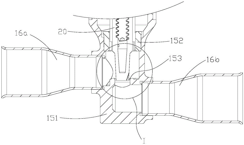
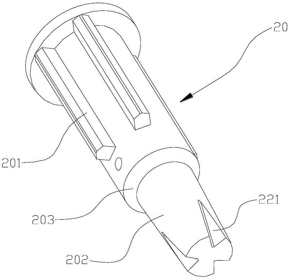
[0040] The core of the present invention is to provide an electronic expansion valve and its valve core. The structural design of the valve core can reduce the area of ​​the vortex area formed at the bottom of the valve core when the opening is large, increase the effective flow area of ​​the fluid, and reduce the The effect of flow regulation.

[0041] In order to enable those skilled in the art to better understand the solution of the present invention, the present invention will be further described in detail below in conjunction with the accompanying drawings and specific embodiments.

[0042] For ease of understanding and brevity of description, the electronic expansion valve and its valve core will be described together below, and the beneficial effects will not be discussed again.

[0043] In this embodiment, the structure of the electronic expansion valve can refer to figure 1 and figure 2 It is understood that the electronic expansion valve includes a driving part ...


PUM


Abstract

The invention discloses an electronic expansion valve and a valve core thereof. The valve core comprises a driving connection part and a flow adjusting part fixedly arranged under the driving connection part; the overall flow adjusting part is of an inverted circular truncated cone structure; and the lower end of the flow adjusting part is provided with at least one flow guide groove in the circumferential direction, and the flow guide grooves penetrate through the bottom end surface of the flow adjusting part. According to the valve core, the lower end of the flow adjusting part of the valve core is provided with the at least one flow guide groove penetrating through the bottom end surface of the flow adjusting part in the circumferential direction, in this way, when the opening degree of the valve core reaches a certain degree, the area of an eddy current zone on the lower portion of the flow adjusting part is decreased through the design of the flow guide grooves, the effective circulation area of a refrigerant is increased, and the influence on flow adjusting is reduced; and in addition, as the area of the eddy current zone is decreased, cavitation at the eddy current position is reduced correspondingly, and the fluid noise can be effectively lowered.

Description

technical field [0001] The invention relates to the technical field of fluid control components, in particular to an electronic expansion valve and a valve core thereof. Background technique [0002] Generally, an electronic expansion valve includes a driving part, a gear assembly, a screw rod, a valve core and a valve seat assembly. [0003] The output shaft of the driving part is connected to the screw rod through the gear assembly, and the screw rod is threadedly connected to the valve core, wherein the circumferential direction of the valve core is limited. [0004] The valve seat of the valve seat assembly is provided with interfaces connected with two connecting pipes respectively. One of the two connecting pipes is a fluid inlet and the other is a fluid outlet. The valve seat also has a valve port, which controls the opening and closing of the valve port. On-off of two interfaces. [0005] A valve core seat is embedded in the valve seat, and a flow port connecting t...

Claims


Application Information

Patent Timeline
IPC IPC(8): F16K1/36
CPCF16K1/36F25B41/35F16K1/38F16K47/04F16K47/06F16K1/52F16K1/54Y02B30/70F16K1/2263F16K1/422F16K25/005F16K27/0263
Inventor 不公告发明人
Owner 浙江三花商用制冷有限公司
Why Eureka
Try Eureka