Active padlock

A lock body and lock nose technology, applied in the field of door locks, can solve problems such as too many parts, difficult production and assembly, complex structure of intelligent locks, etc., and achieve the effect of improving automation

Inactive Publication Date: 2017-06-23
青岛凯福智能科技有限公司
View PDF7 Cites 5 Cited by
  • Summary
  • Abstract
  • Description
  • Claims
  • Application Information

AI Technical Summary

Problems solved by technology

[0005] The above-mentioned smart locks add electronic management and other functions on the basis of traditional mechanical locks. Although the safety performance has been greatly improved; however, the current smart locks have complex structures, too many parts, and difficult production and assembly.

Method used


Image

  • Active padlock
  • Active padlock
  • Active padlock

Examples


Embodiment 1

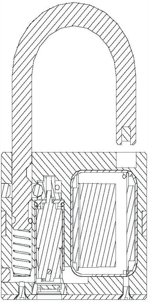
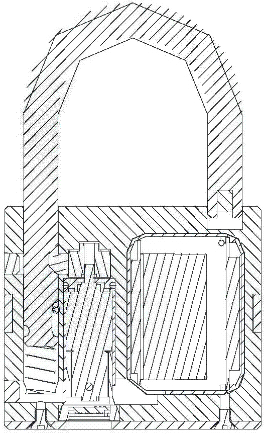
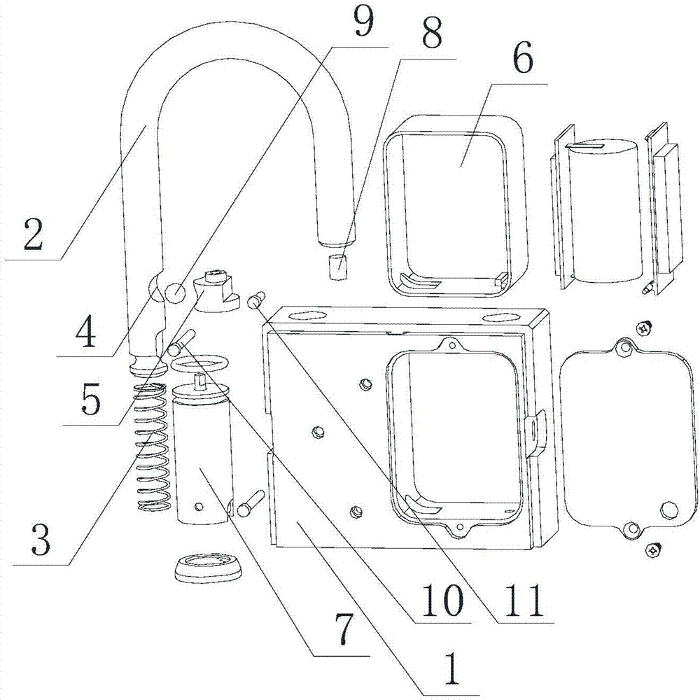
[0019] Example 1, such as Figure 1-3 As shown, this embodiment discloses an active padlock, comprising a lock body 1 and a lock nose 2 installed on the lock body, the lock body is provided with a lock hole corresponding to the key, a cavity is provided in the lock body, and a cavity is provided in the cavity. A spring 3 is arranged at the bottom of the cavity, and one end of the lock nose is inserted into the above-mentioned cavity against the spring at the bottom, and a slot 4 is set at the part where the lock nose is located in the cavity, and a cam 5 with a groove is set in the lock body adjacent to the slot, Steel ball 9 is set in the groove of cam, and cam counterclockwise rotation can push steel ball in the draw-in groove, and padlock is closed; A power supply 6 is arranged in the lock body. As an alternative, in this embodiment, the power supply is placed in the power supply box. The circuit board that is electrically connected with the power supply and the drive moto...


PUM


Abstract

The invention discloses an active padlock. The active padlock comprises a lock body and a lock strike mounted on the lock body, a lock hole corresponding to a key is formed in the lock body, a cavity is formed in the lock body, a spring is arranged at the bottom of the cavity, one end of the lock strike is inserted into the cavity to abut against the bottom spring, a clamping groove is formed in the part, located in the cavity, of the lock strike, a cam with a groove is arranged at the position, close to the clamping groove, in the lock body, and a steel ball is arranged in a groove of the cam. According to the active padlock, an electronic control driving motor of a circuit board is additionally arranged, the unlocking and locking states of the lock are monitored in real time, and the wireless emission and abnormity alarm functions and the like are provided; the motor is driven to realize unlocking and locking, so that the automation is improved; and a first positioning pin can prevent the lock strike from being disengaged from the cavity of the lock body, and a second positioning pin can play a limiting role so as to limit the rotation angle of the cam.

Description

technical field [0001] The invention belongs to the field of door locks, and in particular relates to an active padlock in the field. Background technique [0002] Locks are not only daily necessities for human beings, but also represent the culture of a country and nation in different historical periods. From the early ropes, wooden locks, and metal locks; to the current mechanical locks, combination locks, electronic locks, etc., different functions are realized by designing different internal structures. [0003] Chinese invention patent application CN103824365A discloses a smart padlock based on RFID technology, including no less than one handheld RFID terminal, a smart padlock management system and no less than one RFID smart padlock; the handheld RFID terminal intersects with the RFID smart padlock At the same time, the handheld RFID terminal is also connected to the smart padlock management system respectively; after the handheld RFID terminal is close to the RFID sm...

Claims


Application Information

Patent Timeline
IPC IPC(8): E05B67/00E05B49/00E05B47/00
CPCE05B47/0012E05B49/00E05B67/00E05B2047/0058
Inventor 梁军波
Owner 青岛凯福智能科技有限公司
Why Eureka
Try Eureka