


Quick Research
Generate reliable direction feasibility study reports for your R&D in just a few steps.

Technical Q&A
Discover and master advanced knowledge NOW. Basics, ideas, possibilities, all at once.

Find Solutions
As an expert in R&D theories, this can generate solutions to your technical problems instantly.

Evaluate Feasibility
Analyze your overall solution with one click, know your potential R&D risks in advance.

Monitor Landscape
Get weekly tech updates, stay abreast of the latest tech innovations and key insights.
Transfer arm for mobile transport of billets on cooling beds
A technology of steel billet and cooling bed, applied in the field of moving steel arm, can solve the problems of shortening the transportation time of steel moving arm transport teeth and conveyor belt, covering a large area, and setting up another motor for steel moving arm, etc., so as to shorten the transportation time, The effect of prolonging service life and improving transportation efficiency
- Summary
- Abstract
- Description
- Claims
- Application Information
AI Technical Summary
Problems solved by technology
Method used
Image

Examples
Embodiment 1
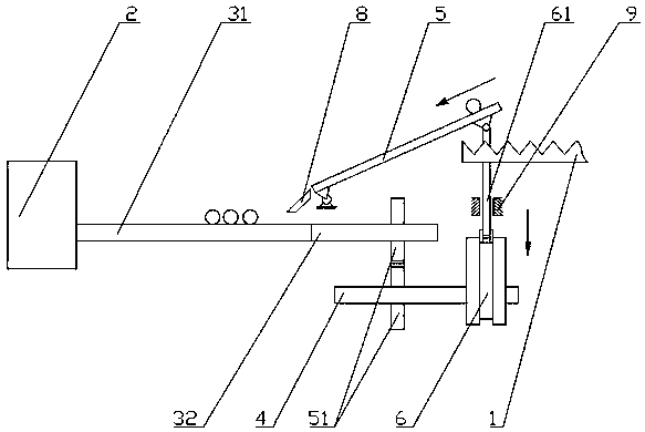
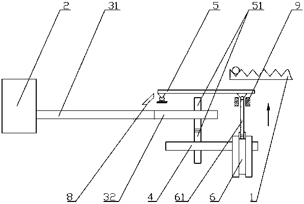
[0034] Such as figure 1 with 2 As shown, the moving steel arm used for the mobile transportation of the cooling bed billet includes a fixed frame, a motor 2, a transportation main shaft, a wheel shaft 4 and a steel arm main body 5, the motor 2 drives the transportation main shaft, and the transportation main shaft includes a conveying part 31 and a transmission part 32, The transmission part 32 of the wheel shaft 4 and the transport main shaft is provided with a gear 51, and the transport main shaft drives the wheel shaft 4 through the meshing of the gear 51. The wheel shaft 4 is also provided with a cam 6 located below the cooling bed 1, and the cam 6 is also equipped with a material Push rod 61; one end of the steel arm main body 5 is located above the conveying part 31, and is connected to the fixed frame by a hinge, and the other end is hingedly connected with the material push rod 61; the cam 6, the material push rod 61 and the steel arm main body 5 constitute With the c...
Embodiment 2
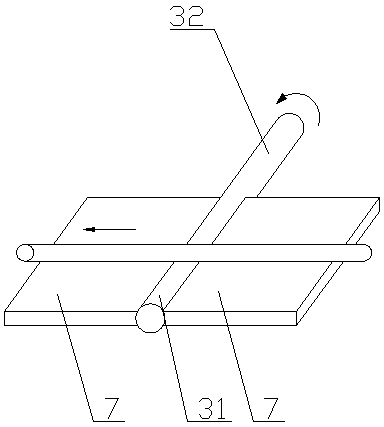
[0036] Such as figure 2 As shown, compared with Example 1, the present embodiment optimizes the conveying part 31. Along the steel billet conveying direction, conveying support plates 7 are provided on both sides of the conveying part 31 of the conveying main shaft. In this embodiment, conveying The support plate 7 can further help the transport main shaft to transport the steel billet, preventing the steel billet from falling from the transport support plate 7.
Embodiment 3
[0038] Such as figure 1 with 2 As shown, compared with Example 2, the present embodiment has added a buffer swash plate 8, and a buffer swash plate 8 is also provided between the steel arm main body 5 and the transportation support plate 7, and a buffer swash plate 8 that buffers the steel billet slides down, and one end of the buffer swash plate 8 is connected to the steel The blanking end of the arm main body 5 is connected, and the other end is located on the transport support plate 7. In this embodiment, the buffer slant plate 8 can prevent the steel billet from falling on the transport support plate 7 when it slides from the steel arm main body 5, reducing the The impact force of the steel billet, thereby protecting the conveying part 31 and the conveying support plate 7 on the conveying main shaft, thereby prolonging the service life.
PUM
 Abstract
Description
Claims
Application Information
 - R&D Engineer
- R&D Manager
- IP Professional
- Industry Leading Data Capabilities
- Powerful AI technology
- Patent DNA Extraction
Browse by: Latest US Patents, China's latest patents, Technical Efficacy Thesaurus, Application Domain, Technology Topic, Popular Technical Reports.
© 2024 PatSnap. All rights reserved.Legal|Privacy policy|Modern Slavery Act Transparency Statement|Sitemap|About US| Contact US: help@patsnap.com