
Control method and system for automatically compensating pipe end liquid leakage in internal high pressure forming

A technology of internal high-pressure forming and automatic compensation, which is applied in the field of pipe forming processing, can solve the problems of leak detection, leakage, and pressure detection methods that cannot be used, and achieve the effect of improving the yield and restoring the seal of the pipe end

Active Publication Date: 2018-08-14
HARBIN INST OF TECH
View PDF3 Cites 0 Cited by
  • Summary
  • Abstract
  • Description
  • Claims
  • Application Information

AI Technical Summary

Problems solved by technology

[0016] The liquid leakage generated during high pressure forming cannot be introduced into the closed volume, so this method cannot be used for leak detection
[0017] Patent CN201610673810.2 discloses a pipeline leakage detection system and its method. The distributed optical fiber temperature field measurement technology is used to detect pipeline leakage. The measurement device cannot be installed in the internal high pressure forming mold, so the leakage in the internal high pressure forming process cannot be detected. detection
[0018] The above liquid leakage detection method is only suitable for static pipeline leakage detection, and it takes a long time to detect the leakage. However, the pressurization process during internal high pressure forming is completed in a very short time, and the pressurization process is only 4s- 6s, the dynamic change of pressure is very fast, and the pressure detection methods in the prior art cannot be used for the detection of slight leakage that occurs during the internal high pressure forming process and cannot be judged from the pressure value

Method used


Image

  • Control method and system for automatically compensating pipe end liquid leakage in internal high pressure forming
  • Control method and system for automatically compensating pipe end liquid leakage in internal high pressure forming
  • Control method and system for automatically compensating pipe end liquid leakage in internal high pressure forming

Examples


Embodiment 1

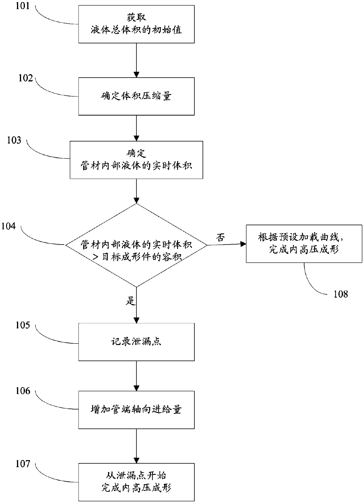
[0070] like figure 1 As shown, the control method for automatically compensating for liquid leakage at the pipe end in internal high pressure forming includes the following steps:

[0071] Step 101: Obtain the initial value of the total volume of the liquid in the high-pressure chamber of the supercharger, the liquid inside the pipe, and the liquid inside the high-pressure pipeline at the start of the internal high-pressure forming;

[0072] Step 102: Determine the volume compression of the total volume according to the initial value of the total volume and the real-time pressure of the liquid inside the pipe;

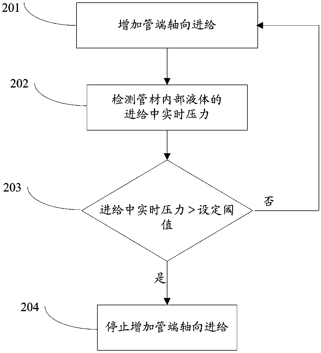
[0073] Step 103: Determine the real-time volume of the liquid inside the pipe according to the volume compression, the initial value of the total volume, the real-time volume of the liquid in the high-pressure chamber under the real-time pressure, and the real-time volume of the liquid inside the high-pressure pipeline; wherein, the real-time volume of the liquid in th...

Embodiment 2

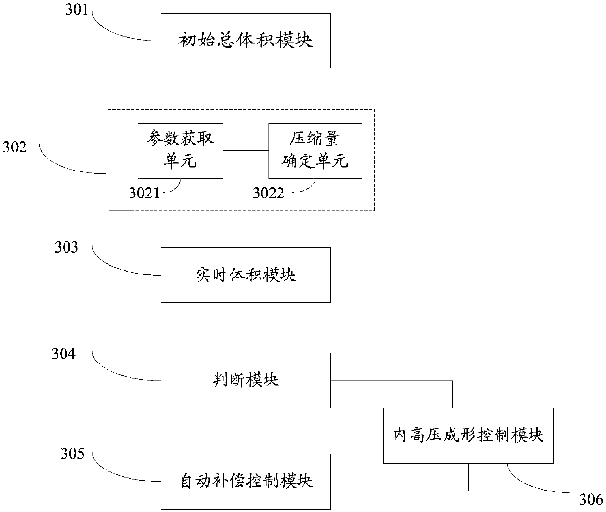
[0090] Such as image 3 As shown, the control system for automatically compensating the liquid leakage at the pipe end in internal high pressure forming includes:

[0091] The initial total volume module 301 is used to obtain the initial value of the total volume of the liquid in the high-pressure chamber of the supercharger, the liquid inside the pipe, and the liquid inside the high-pressure pipeline at the beginning of the internal high pressure forming;

[0092] A volume compression module 302, configured to determine the volume compression of the total volume according to the initial value of the total volume and the real-time pressure of the liquid inside the pipe;

[0093] A real-time volume module 303, configured to use the volume compression amount, the initial value of the total volume, the real-time volume of the liquid in the high-pressure chamber under the real-time pressure, and the real-time volume of the liquid inside the high-pressure pipeline determining the ...

Embodiment 3

[0102] Such as Figure 4 As shown, the controller 10 for automatically compensating the liquid leakage at the pipe end in the internal high pressure forming is used to control the internal high pressure forming machine 401. The controller 10 includes: an initial total volume module, a volume compression module, a real-time volume module, a judgment module, and an automatic compensation Control module and internal high pressure forming control module.

[0103] Such as Figure 4 As shown, the left punch 5 is installed on the left servo cylinder 6, the left servo cylinder 6 is installed with a built-in first displacement sensor 7, the left servo cylinder 6 is controlled by the first proportional servo valve 8, and the right punch 2 is installed on the right servo cylinder 22, the right servo cylinder 22 is equipped with a built-in second displacement sensor 21, and the right servo cylinder 22 is controlled by the second proportional servo valve 12.

[0104] The principle of sup...


PUM

PropertyMeasurementUnit
thicknessaaaaaaaaaa
lengthaaaaaaaaaa
thicknessaaaaaaaaaa

Abstract

The invention discloses a control method and a system for liquid leakage from a pipe end in automatic compensation internal high pressure forming. The control method comprises obtaining the initial value of the total volume of liquid in a high pressure chamber of a supercharger, liquid in a pipe and liquid in a high pressure piping at the beginning of the internal high pressure forming; determining the compression amount of the total volume of the liquid according to the initial value of the total volume and the real-time pressure of the liquid in the pipe; determining the real-time volume of the liquid in the pipe; judging whether the real-time volume of the liquid in the pipe is larger than the final volume of a target formed part; if larger than the final volume, record leakage points, increase the axial feed amount of the pipe end to the pipe end for resealing, and finish the internal high pressure forming starting from the leakage point according to the preset displacement-internal pressure loading curve; if not, finish the internal high pressure forming according to the preset displacement-internal pressure loading curve. The leakage condition of the pipe end can be precisely judged by using the control method and the system disclosed by the invention, and automatic compensation is made through increasing the axial feed of the pipe end.

Description

technical field [0001] The invention relates to the field of pipe forming and processing, in particular to a control method and system for automatically compensating for pipe end liquid leakage during internal high pressure forming. Background technique [0002] Internal high pressure forming technology is an advanced pipe forming process. Its principle is to apply internal pressure and axial force to the pipe, so that the pipe is plastically deformed and attached to the mold cavity, and formed into a pipe fitting of the desired shape. [0003] The highest internal pressure in the high pressure forming process reaches 300MPa-400MPa, which must be provided by a supercharger. At the same time, it is necessary to match the internal pressure with the axial displacement to achieve the preset displacement-internal pressure loading curve. The internal pressure control principle is to indirectly control the liquid pressure in the high-pressure chamber of the supercharger by controll...

Claims


Application Information

Patent Timeline
Patent Type & Authority Patents(China)
IPC IPC(8): B21D26/033B21D26/041
CPCB21D26/033B21D26/041
Inventor 苑世剑王小松贺久强
Owner HARBIN INST OF TECH
Learn More