
Dissection type 3D printing net-shaped skull patch

A 3D printing, anatomical technology, applied in the fields of skull, bone implants, medical science, etc., can solve the problems of high incidence of intracranial effusion, poor anatomical matching, difficult puncture and extraction, etc. Incidence of effusion and infection, effect of promoting repair and healing, reducing the risk of cutting injury

Inactive Publication Date: 2017-06-20
武汉康酷利科技有限公司
View PDF14 Cites 8 Cited by
  • Summary
  • Abstract
  • Description
  • Claims
  • Application Information

AI Technical Summary

Problems solved by technology

[0003] At present, the commonly used cranial repair prosthesis is titanium alloy mesh and polyetheretherketone mesh. Alloy mesh has the advantages of non-toxicity, low inflammation and sensitization, but there are still the following disadvantages: titanium mesh is often prepared by manual shaping, the process is rough, the process is cumbersome, and the anatomical matching is poor. Good thermal conductivity, while the firmness is not high enough, which limits its further development in the clinic; PEEK patch is a newly developed new implant to replace the titanium alloy mesh, which makes up for the poor thermal insulation and strength of the titanium alloy mesh. Not high disadvantages, but also has the advantages of good biocompatibility and good shape fit, so it gradually began to be used in clinical practice, but in the process of clinical application, it was found that the incidence of subcutaneous and intracranial effusion was high, and once it occurred For such complications, doctors and patients often face the dilemma of having to take out the prosthesis, because the PEEK prosthesis usually has fewer and deeper holes than titanium alloy mesh, and the diameter of the cavity is smaller, so it is very difficult to puncture and pump fluid. Large, the success rate is very low, so this disadvantage limits its wide application in clinical

Method used


Image

  • Dissection type 3D printing net-shaped skull patch
  • Dissection type 3D printing net-shaped skull patch
  • Dissection type 3D printing net-shaped skull patch

Examples


Embodiment Construction

[0052] The present invention will be further described below in conjunction with the accompanying drawings and specific embodiments.

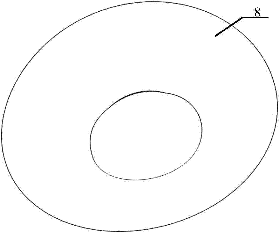
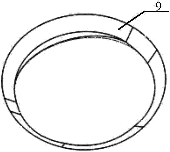
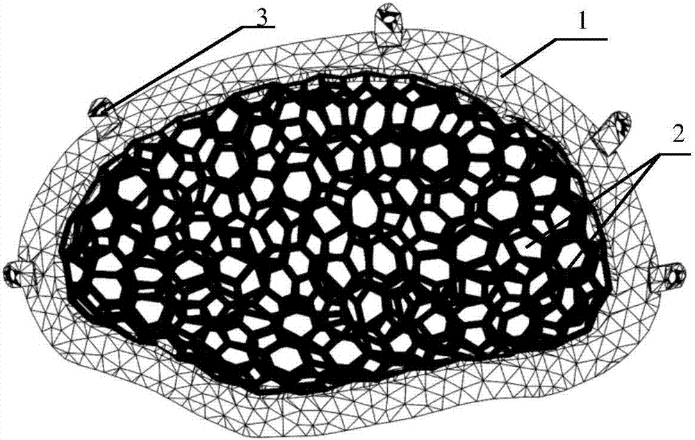
[0053] Figure 1 to Figure 6 They are schematic diagrams of the six structures of the anatomical 3D printed mesh skull patch of the present invention.

[0054] Such as figure 1 As shown, the anatomical 3D printed mesh skull patch includes a skull patch edge 1 and a skull patch mesh structure 2 that match the brain injury site; the skull patch edge 1 is a non-porous belt Tentacle structure, tentacle 3 with counterbore 7, such as Figure 13 As shown, the cross-sectional shape of the counterbore 7 is a trapezoidal structure; the mesh structure 2 of the skull patch is composed of a beam structure 4 (such as Figures 9 to 11 Shown) is a continuous mesh formed by random interweaving of multi-layer meshes.

[0055] Such as figure 2 As shown, the anatomical 3D printed mesh skull patch includes a skull patch edge 1 and a skull patch mesh structure...


PUM


Abstract

The invention discloses a dissection type 3D printing net-shaped skull patch, and belongs to the technical field of skull repair. The skull patch comprises a skull patch edge matched with a brain injured part and a skull patch mesh structure, the skull patch edge is of a porous tentacle-free structure or pore-free tentacle-free structure or a pore-free tentacle structure. The skull patch mesh structure is formed by randomly weaving single-layer meshes or multi-layer meshes formed by beam structures. The skull patch is matched with the shape and dimension height of an original skull defect portion, and has the good anatomy and biological compatibility; meanwhile, the porous net-shaped design can effectively improve internal and external blood supply of the skull, after the skull patch is implanted, subcutaneous hematoma hematoma puncture drainage difficulty are likely to occur, the dropsy and infection occurrence rate can be lowered, and repairing and healing are promoted.

Description

technical field [0001] The invention relates to the technical field of skull repair, in particular to an anatomical 3D printed mesh skull patch. Background technique [0002] Skull defects are mostly one of the postoperative sequelae of common diseases such as craniocerebral injury, cerebrovascular accident, and intracranial tumor. The purpose of cranial defect repair and plastic surgery is not only to prevent re-injury of brain tissue and restore the physiological airtightness of the cranial cavity, but also to restore the original appearance of the patient and meet the aesthetic requirements, which has good physiological and psychological significance. [0003] At present, the commonly used cranial repair prosthesis is titanium alloy mesh and polyetheretherketone mesh. Alloy mesh has the advantages of non-toxicity, low inflammation and sensitization, but there are still the following disadvantages: titanium mesh is often prepared by manual shaping, the process is rough, t...

Claims


Application Information

Patent Timeline
IPC IPC(8): A61F2/28B33Y80/00
CPCA61F2/2875A61F2002/2835A61F2310/00293A61F2310/00359B33Y80/00
Inventor 吴卫东雷霆舒凯牛洪泉曹荣辉黄登峰潘智勇
Owner 武汉康酷利科技有限公司
Learn More