
Apparatus and method for controlling variable valve timing in an internal combustion engine

An internal combustion engine and valve timing technology, applied to internal combustion piston engines, combustion engines, mechanical equipment, etc., can solve problems such as damage to catalyst devices, and achieve the effect of reducing torque loss and preventing damage.

Active Publication Date: 2021-08-03
HYUNDAI MOTOR CO LTD
View PDF5 Cites 0 Cited by
  • Summary
  • Abstract
  • Description
  • Claims
  • Application Information

AI Technical Summary

Problems solved by technology

Therefore, the temperature of the catalyst increases so that the catalyst device 40 may be damaged

Method used


Image

  • Apparatus and method for controlling variable valve timing in an internal combustion engine
  • Apparatus and method for controlling variable valve timing in an internal combustion engine
  • Apparatus and method for controlling variable valve timing in an internal combustion engine

Examples


Embodiment Construction

[0028] Hereinafter, with reference to the accompanying drawings, exemplary embodiments according to the present disclosure will be described in detail.

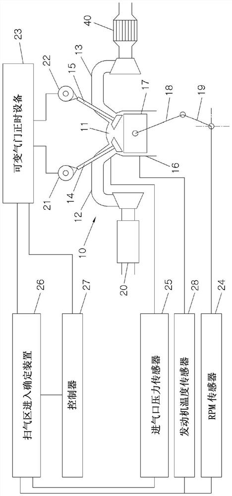
[0029] figure 1 is a diagram showing a rough system configuration of an apparatus for controlling variable valve timing in an internal combustion engine according to the present disclosure.

[0030] Inside a cylinder 16 of the engine 10 , a piston 17 connected to a crankshaft 19 through a connecting rod 18 is provided, and an inner space of the cylinder 16 above an upper portion of the piston 17 forms a combustion chamber 11 .

[0031] Turbocharger 20 may be mounted upstream of intake 12 of engine 10 . The turbocharger 20 may suck in and compress exhaust gas or outdoor air through an unillustrated compressor, and supply air supercharged by this process to the combustion chamber 11 through the intake port 12 .

[0032] Charged air supplied from the intake port 12 may be mixed with fuel supplied through an unshown fuel injec...


PUM


Abstract

An apparatus for controlling variable valve timing in an internal combustion engine that varies the opening and closing of intake and exhaust valves by controlling the rotational phase of the crankshaft relative to the crankshaft of the internal combustion engine time, the apparatus includes a controller configured to determine whether the engine state enters the scavenging region in the overlapping region of the intake valve and the exhaust valve and controls the variable valve timing to The period of time elapsed after the zone, reducing the valve overlap time.

Description

[0001] Cross References to Related Applications [0002] This application claims the benefit of Korean Patent Application No. 10-2015-0173877 filed with the Korean Intellectual Property Office on December 8, 2015, the entire contents of which are hereby incorporated by reference. technical field [0003] The present disclosure relates to an apparatus and method for controlling variable valve timing (VVT) in an internal combustion engine, and more particularly, to such a method for controlling variable valve timing (VVT) in an internal combustion engine Devices for timing: their ability to prevent catalyst damage during scavenging (scavenging) conditions, in which fresh air is delivered directly from the intake to the exhaust of the engine; and methods thereof. Background technique [0004] In recent years, internal combustion engines are equipped with a turbocharger and an intercooler in order to reduce fuel consumption and obtain a large output. In such an internal combust...

Claims


Application Information

Patent Timeline
Patent Type & Authority Patents(China)
IPC IPC(8): F02D13/02
CPCF02D13/0215F02D13/0261F01L1/344F01L2800/00F02D13/0219F02D41/0007F02D2041/001F02D2200/0406F02D2200/101Y02T10/12Y02T10/40
Inventor 文治皓黄圭敏
Owner HYUNDAI MOTOR CO LTD
Learn More