
Motor drive system based on sliding-mode observer

A technology of motor drive system and sliding mode observer, used in motors, electric vehicles, control systems, etc., can solve the problems of unstable vehicle speed, reduced system reliability, and large loss of switching tubes, so as to ensure smooth operation and improve response. speed, the effect of reducing system cost

Pending Publication Date: 2017-06-13
王丛森
View PDF0 Cites 4 Cited by
  • Summary
  • Abstract
  • Description
  • Claims
  • Application Information

AI Technical Summary

Problems solved by technology

In this control mode, the response speed of the system is slow, and overshooting is easy to occur during the adjustment process, and the actual speed vibrates around the set value for a long time, which causes the driver to feel that the speed of the vehicle is unstable during the speed-up process.
Mechanical position sensors can achieve high-precision detection of the rotor position, but they are usually expensive and easily limited by environmental conditions, and have disadvantages such as increasing the moment of inertia of the motor rotor, increasing the system volume, and reducing system reliability.
In addition, current electric vehicles generally use a chopper boost (boost) method to boost the output voltage of the battery. This method has large switching tube losses and low power factor.

Method used


Image

  • Motor drive system based on sliding-mode observer
  • Motor drive system based on sliding-mode observer
  • Motor drive system based on sliding-mode observer

Examples


Embodiment Construction

[0015] In order to make the above-mentioned purposes, features and advantages of the present invention more obvious and understandable, the specific implementation modes of the present invention will be described in detail below in conjunction with the accompanying drawings, so that the above-mentioned and other purposes, features and advantages of the present invention will be clearer. Like reference numerals designate like parts throughout the drawings. The drawings have not been drawn to scale, emphasis instead being placed upon illustrating the gist of the invention.

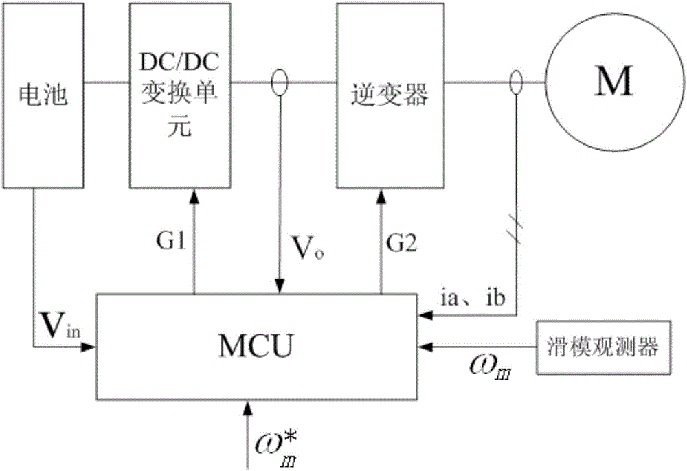
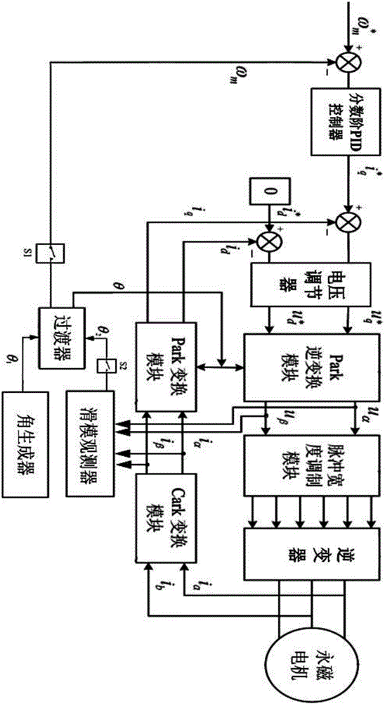
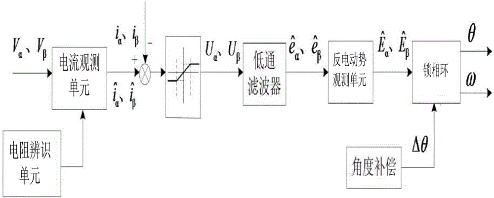
[0016] first combined with figure 1 The system structure of the present invention will be described. The invention provides an electric vehicle driving system, which includes: a DC / DC conversion unit, an inverter, a permanent magnet motor, an MCU (main control unit), an angle generator, a sliding mode observer and the like. The DC / DC conversion unit is connected to the battery, the output end of the DC / DC ...


PUM


Abstract

The invention discloses a motor drive system based on a sliding-mode observer. The motor drive system comprises a DC / DC conversion unit, an inverter, a permanent magnet motor, an MCU, an angle generator and the sliding-mode observer; the DC / DC conversion unit is connected with a battery, the output end of the DC / DC conversion unit is connected with the inverter, and the inverter is connected with the permanent magnet motor; the input voltage Vin and the output voltage Vo of the DC / DC conversion unit are detected through a voltage sensor, the output voltages ia and ib of the inverter are detected through a current sensor, the rotating speed omega<m> and the rotor position of the permanent motor are observed through the sliding-mode observer, a specific angle is generated in the motor starting stage through the angle generator, and therefore the motor can be successfully started. Accordingly, the control effect of the system is improved.

Description

technical field [0001] In general, the present invention relates to motors, and in particular to a motor drive system based on a sliding mode observer. Background technique [0002] Electric vehicles, such as electric cars, are becoming more and more popular. At present, the drive of electric vehicles generally adopts the mode of battery + permanent magnet motor, and the control system adopts open-loop / closed-loop control. For open-loop control, the vehicle (vehicle speed) cannot accurately follow the given, which has been phased out. In the closed-loop control, the speed closed-loop control method is generally adopted at present, which uses the traditional PID regulator to adjust the deviation between the given speed and the actual speed, and controls the output of the inverter according to the adjustment result. With this control method, the system response speed is slow, and overshoot is prone to occur during the adjustment process, and the actual speed vibrates around ...

Claims


Application Information

Patent Timeline
Patent Type & Authority Applications(China)
IPC IPC(8): H02P6/08H02P6/20H02P6/00H02P21/00H02P21/18H02P21/34B60L15/20
CPCB60L15/20H02P6/005H02P6/08H02P6/20H02P21/0007H02P2203/03Y02T10/64Y02T10/72
Inventor 不公告发明人
Owner 王丛森
Learn More