Eureka AIR delivers breakthrough ideas for toughest innovation challenges, trusted by R&D personnel around the world.

Control circuit of switch power supply and method thereof

A switching power supply and control circuit technology, applied in the direction of control/regulation systems, electrical components, and adjustment of electrical variables, can solve the problems of increasing control circuit pins and power system design costs, poor constant current accuracy, and large output current differences.

Active Publication Date: 2017-06-13
WUXI CHIPOWN MICROELECTRONICS
View PDF7 Cites 20 Cited by
  • Summary
  • Abstract
  • Description
  • Claims
  • Application Information

AI Technical Summary

Problems solved by technology

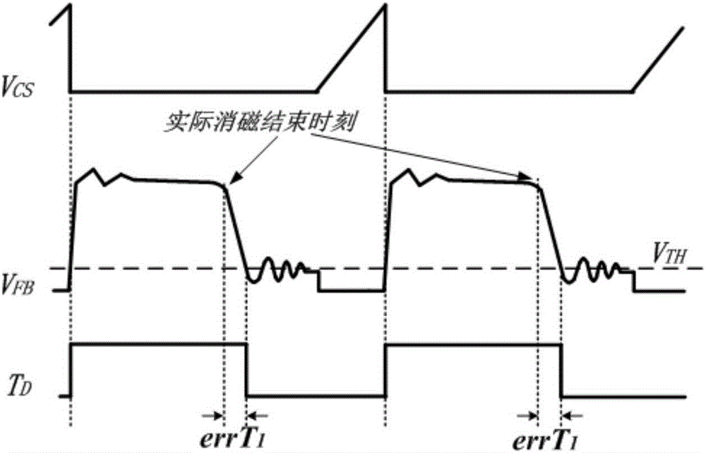
[0008] To sum up, the above working method not only increases the design cost of control circuit pins and power system, but also has disadvantages such as large output current difference between working modes, low input voltage adjustment rate, and poor constant current accuracy.

Method used


Image

  • Control circuit of switch power supply and method thereof
  • Control circuit of switch power supply and method thereof
  • Control circuit of switch power supply and method thereof

Examples


Embodiment Construction

[0050] In order to have a clearer understanding of the technical features, purposes and effects of the present invention, specific implementations will now be described in detail with reference to the accompanying drawings.

[0051] The control circuit of switching power supply and its power supply system, such as Figure 4 As shown, the power system includes transformer T1, output diode D1, output capacitor C O , resistance R FB1 , resistance R FB2 , resistance R CS And the control circuit, the pin FB of the control circuit is connected with the resistor R FB1 , resistance R FB2 Connected, the pin CS of the control circuit is connected to the resistor R CS Connected, the pin SW of the control circuit is connected to the primary side N of the transformer T1 P connected.

[0052] The control circuit includes a first comparator 1, a first RS latch G1, a constant current control module 8, a constant current accuracy compensation module 9, a sample and hold module 10, a low...


PUM


Abstract

The invention discloses a control circuit of a switch power supply and a method thereof. The method comprises the following steps: a constant-current control module generates and outputs a control signal for controlling an output current of the switch power supply according to feedback information on a pin FB and a pin CS, adjusts a power-on duty ratio of a power transistor, and adjusts an output current IO of a power supply system as a constant value; a constant-current precision compensation module adjusts a circuit calculation parameter of the constant-current control module and a sampling and holding module according to the feedback information on the pin FB and the pin CS, so that the output constant-current precision is not influenced by the change of a working mode and / or the change of an input condition; a timer determines a moment when the voltage VFB on the pin FB reaches a peak value; and a pressure control oscillator adjusts the switching frequency of a power transistor according to a control signal outputted by the constant-current control module and an output signal of the timer, so that the switch power supply works at a QR mode or a CCM mode, and when the output voltage is changed, the QR mode is kept unchanged or the current continuous depth of the CCM mode is kept similar.

Description

technical field [0001] The invention relates to a control circuit of a switching power supply and a method thereof, which are suitable for a power supply management integrated circuit system and belong to the technical field of power semiconductors. Background technique [0002] The output current of a flyback switching power supply can be expressed as: in, is the turns ratio of the primary and secondary sides of the transformer, I PRI_PK is the peak value of primary current during transformer excitation, I PRI_O is the initial value of primary current during transformer excitation, T D is the transformer degaussing time, T P is the single switching cycle time of the flyback switching power supply. This expression can also be expressed as: Among them, R CS is the resistance value of the primary side current detection resistor, V CS_PK R for the transformer excitation period CS The peak value of the voltage across the terminal, V CS_O R for the transformer excita...

Claims


Application Information

Patent Timeline
Patent Type & Authority Applications(China)
IPC IPC(8): H02M3/335
CPCH02M3/33523H02M3/33507H02M1/08H02M1/0003
Inventor 李海松赵倡申刘文亮易扬波周飙张韬芮华政
Owner WUXI CHIPOWN MICROELECTRONICS
Why Eureka
Eureka Blog
Learn More