
Broadband circularly polarized microstrip antenna array with C waveband gap coupled feeding

A technology of coupled feeding and microstrip antennas, which is applied to antenna arrays, specific array feeding systems, antennas, etc., can solve the problems of narrow axial ratio bandwidth, large space size, and large feeder loss, and achieve low profile and weight Light and small effect

Pending Publication Date: 2017-06-13
NO 54 INST OF CHINA ELECTRONICS SCI & TECH GRP
View PDF9 Cites 13 Cited by
  • Summary
  • Abstract
  • Description
  • Claims
  • Application Information

AI Technical Summary

Problems solved by technology

[0004] The microstrip antenna in the form of an external circularly polarized bridge has a wide operating frequency band and good circular polarization characteristics, but the structure is complex, the space size is large, and the feeder loss is large
[0005] Double feed point, adjust the phase through the length of the microstrip line to realize the circularly polarized microstrip antenna, the structure is simple, and the feeding network is integrated in the design, but due to the adjustment of the phase through the length of the microstrip line, the axial ratio bandwidth is narrow, which is 15%- 20%

Method used


Image

  • Broadband circularly polarized microstrip antenna array with C waveband gap coupled feeding
  • Broadband circularly polarized microstrip antenna array with C waveband gap coupled feeding
  • Broadband circularly polarized microstrip antenna array with C waveband gap coupled feeding

Examples


Embodiment Construction

[0017] The present invention will be further described below in conjunction with accompanying drawing and specific embodiment:

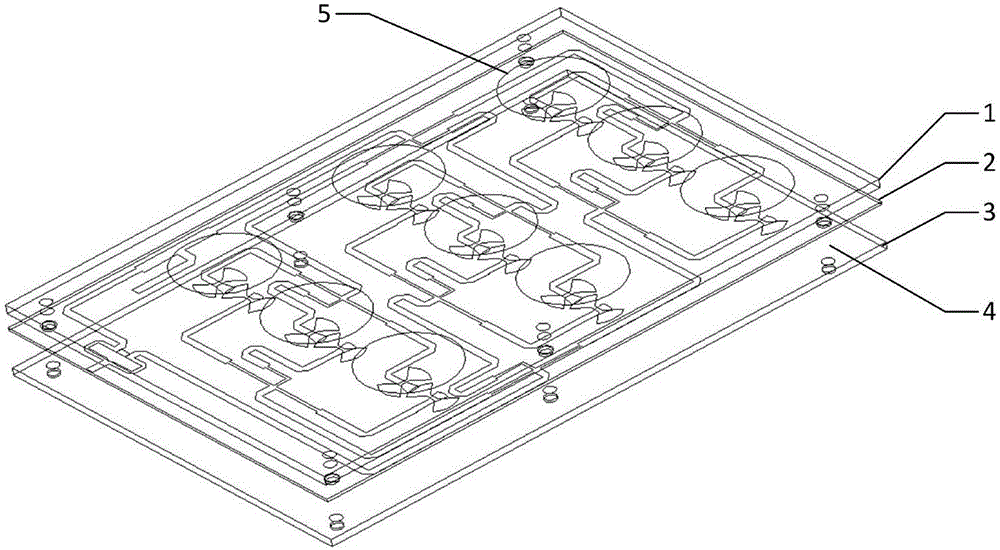
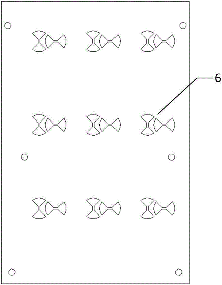
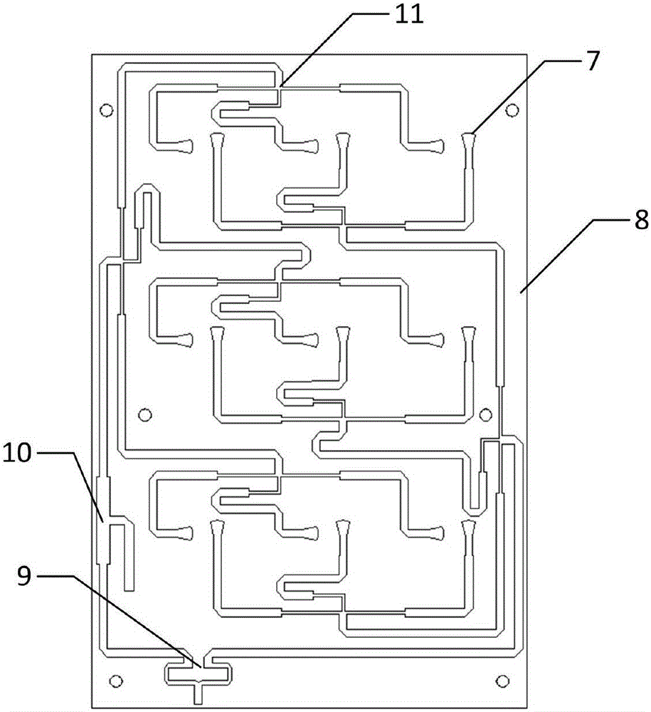
[0018] figure 1 It is a schematic diagram of the structure of the present invention. The present invention consists of a first layer of dielectric board 1, a second layer of dielectric board 2, a third layer of metal reflector and supporting nylon columns 4. The first layer of dielectric board 1 and the second layer of dielectric board 2 Nylon pillars 4 are used to support between the second layer of dielectric board 2 and the third layer of metal reflection board 3; figure 2 is a schematic diagram of the bow-tie coupling structure of the present invention, image 3 It is a schematic diagram of the feeding structure of the present invention.

[0019] The upper surface of the first layer of dielectric board 1 is provided with a plurality of radiation units 5 in the form of patches arranged at equal intervals in the form of several columns; the radi...


PUM


Abstract

The invention relates to a broadband circularly polarized microstrip antenna array with C waveband gap coupled feeding. The broadband circularly polarized microstrip antenna array comprises a first-layer dielectric plate 1, a second-layer dielectric plate 2 placed below the first-layer dielectric plate, a third-layer metal reflecting plate 3, and a supporting nylon column 4. A circular radiating unit 5 is arranged on the upper surface of the first-layer dielectric plate 1, a bow-tie-shaped coupling gap 6 is formed in the upper surface of the second-layer dielectric plate 2, and a feed network 8 and a phase shift network 10 are arranged on the lower surface of the second-layer dielectric plate 2. According to the broadband circularly polarized microstrip antenna array, the technology of the broadband phase shift feed network and the bow-tie-shaped coupling gap is adopted, and the broadband circularly polarized microstrip antenna array has broadband, circular polarization and other electrical performance, and meanwhile is low in weight, small in size, low in section and easy to manufacture.

Description

technical field [0001] The invention provides a wide-band circularly polarized microstrip antenna array for C-band slot coupling feeding, which belongs to the technical field of wireless communication. Background technique [0002] As an important part of the wireless communication system, the performance of the antenna directly affects the performance of the wireless communication system. In aerospace and satellite applications, higher requirements are put forward for the antenna's light weight, broadband, and circular polarization characteristics. At present, microstrip antennas with broadband circular polarization characteristics in wireless communication systems have some shortcomings. [0003] Angle-cut circular polarization antenna, the antenna has a simple structure and light weight, but the working bandwidth is too narrow, only 2%-5%. [0004] The microstrip antenna in the form of an external circularly polarized bridge has a wide operating frequency band and good ...

Claims


Application Information

Patent Timeline
IPC IPC(8): H01Q21/00H01Q1/38H01Q13/08H01Q13/02H01Q1/50
CPCH01Q1/38H01Q1/50H01Q13/0241H01Q13/08H01Q21/00H01Q21/0006
Inventor 焦学强张金波梅立荣马延爽方勇李燕徐珩
Owner NO 54 INST OF CHINA ELECTRONICS SCI & TECH GRP
Learn More