Tunable resonant cavity based on adjustable capacitor

A resonant cavity and capacitor technology, applied in the field of communication, can solve the problems of high cost, low service life and high applied voltage, and achieve the effects of avoiding mechanical fatigue problems, prolonging service life and increasing tuning speed.

Active Publication Date: 2017-06-13
成都迈科科技有限公司
View PDF5 Cites 0 Cited by
  • Summary
  • Abstract
  • Description
  • Claims
  • Application Information

AI Technical Summary

Problems solved by technology

Based on these requirements, the commonly used solution is to use filters with different center frequencies to form a filter bank, but the obvious disadvantage of this solution is that it is expensive and bulky due to the use of multiple filters.
The single tunable filter solution is the most mature tunable filter based on YIG (yttrium iron garnet) technology, but this technology still has disadvantages such as large size, high power consumption, and difficulty in integration.
In addition, tunable filters based on technologies such as varactor diodes, ferroelectric thin films, and planar MEMS (micro-electromechanical systems) have appeared successively, but these filters either cannot meet the wide adjustable range, or cannot achieve high quality factor problem
In recent years, a tunable filter based on an evanescent mode cavity has attracted much attention due to its good quality factor and wide adjustable range; The unique mechanical adjustment method makes it have problems such as low service life, high applied voltage, and center frequency drift.

Method used


Image

  • Tunable resonant cavity based on adjustable capacitor
  • Tunable resonant cavity based on adjustable capacitor
  • Tunable resonant cavity based on adjustable capacitor

Examples


Embodiment Construction

[0020] The present invention will be described in further detail below in conjunction with the accompanying drawings and embodiments.

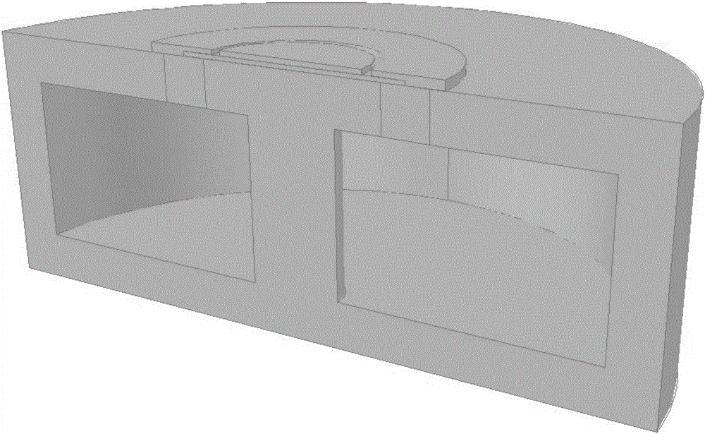
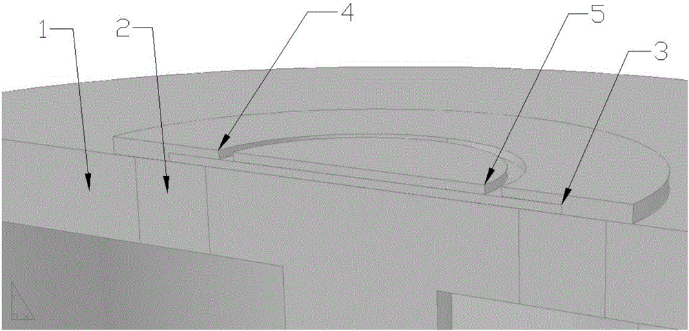
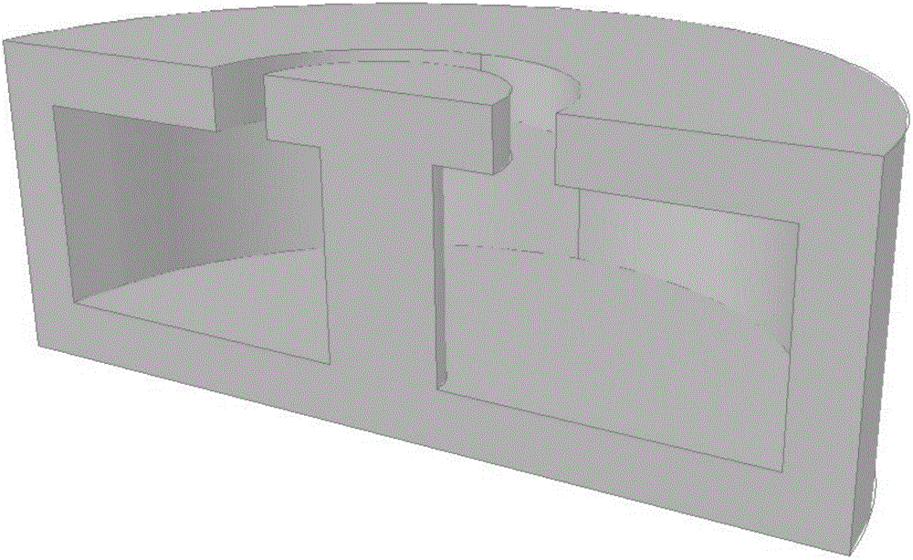
[0021] In this embodiment, an adjustable resonant cavity based on an adjustable capacitor is provided, and its structure is as follows figure 1 , figure 2 As shown; it includes a coaxial-like structure metal cavity 1, an insulating dielectric ring 2, a ferroelectric film 3, a capacitor electrode 4 and a tuning electrode 5; the top of the coaxial-like structure metal cavity has a split ring, and the insulating The dielectric ring is filled into the opening ring; the ferroelectric thin film is arranged in the center above the metal cavity and is circular, and its radius is greater than or equal to the inner radius of the insulating dielectric ring; the tuning electrode is a circular electrode and is arranged on the ferroelectric thin film The upper center; the capacitor electrode is a ring electrode arranged around the tuning electrode, and th...


PUM


Abstract

The invention belongs to the field of communication and provides a tunable resonant cavity based on an adjustable capacitor. The cavity comprises a class coaxial structure metal cavity, an insulating medium ring, a ferroelectric film, a capacitor electrode and a tuning electrode; the top of the class coaxial structure metal cavity is provided with a snap ring filled with the insulating medium ring; the ferroelectric film is arranged in the center of the top of the metal cavity, and the radius is larger than or equal to the inner radius of the insulating medium ring; the tuning electrode is arranged in the center of the top of the ferroelectric film; the capacitor electrode is an annular electrode arranged around the tuning electrode, the outer periphery of the capacitor electrode is connected with the metal cavity, and a parallel capacitor plate structure is formed by the inner periphery of the capacitor electrode, the ferroelectric film and the metal cavity. According to the tunable resonant cavity based on the adjustable capacitor, by the adoption of the adjustable capacitor prepared from the ferroelectric film, firstly, the problem of mechanical fatigue is avoided, the service life of the resonant cavity is prolonged; secondly, the tuning voltage only needs to reach 30 volts, and the tuning is more simple and convenient; finally, because of the extremely high reaction speed of ferroelectric materials, the tuning speed of the resonant cavity is also increased.

Description

technical field [0001] The invention belongs to the communication field and relates to designing an adjustable filter, in particular to an adjustable resonant cavity based on an adjustable capacitance. Background technique [0002] The electromagnetic environment in which electronic communication equipment in modern warfare lives has become more and more complicated, and the threat of interference is becoming more and more serious. The struggle between interference and anti-interference has become the focus of research in modern electronic warfare. Due to the continuous and rapid development of communication technology and the rapid progress of electronic countermeasure technology, the spectrum background of radio communication is becoming more and more complex. It is different from the previous electronic systems: high integration, high intelligence, and the combination of digital and analog signals have become new features of modern electronic systems. The research on the...

Claims


Application Information

Patent Timeline
Patent Type & Authority Applications(China)
IPC IPC(8): H01P1/209
CPCH01P1/209
Inventor 张继华陈建男郑懿陈宏伟
Owner 成都迈科科技有限公司
Why Eureka
Try Eureka