Voltage reduction method and voltage reduction circuit of battery pack

A battery pack and circuit technology, which is applied in the direction of circuits, secondary batteries, secondary battery repair/maintenance, etc., can solve the problems of increasing product design volume, increasing design difficulty, increasing product development cost, etc., and achieving low energy loss , improve stability and safety, and improve conversion efficiency

Pending Publication Date: 2017-06-13
HUIZHOU BNET TECH CO LTD
View PDF10 Cites 0 Cited by
  • Summary
  • Abstract
  • Description
  • Claims
  • Application Information

AI Technical Summary

Problems solved by technology

In order to make up for the conversion loss, more batteries should be added when designing the product, and the conversion loss is converted into heat, so the battery must be cooled, which will increase the design volume of the product and increase the product development cost. It will also increase the difficulty of designing
In addition, as the load current increases in the existing common step-down circuit, the loss will further increase, and the circuit design will be more complicated

Method used


Image

  • Voltage reduction method and voltage reduction circuit of battery pack
  • Voltage reduction method and voltage reduction circuit of battery pack
  • Voltage reduction method and voltage reduction circuit of battery pack

Examples


Embodiment 1

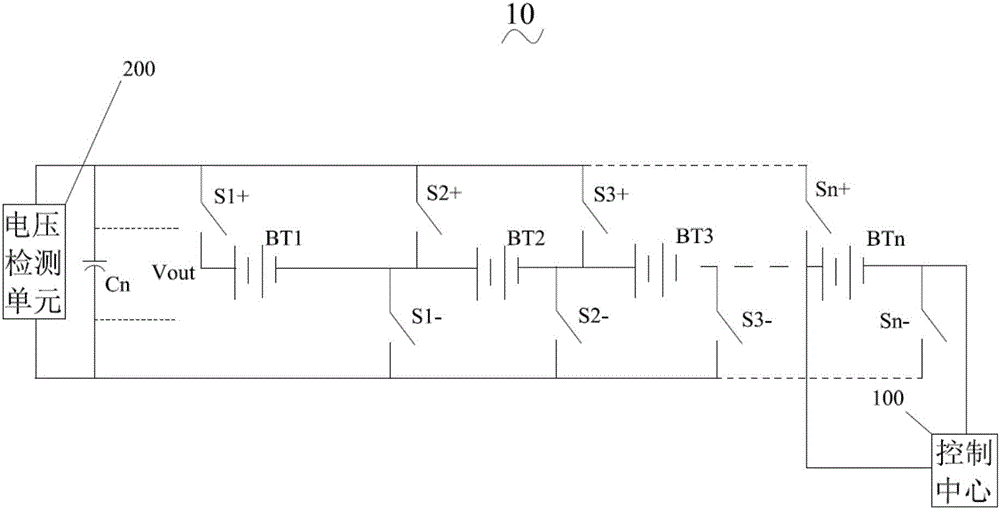
[0052] Please also refer tofigure 1 with figure 2 , The present invention provides a battery pack step-down circuit 10 comprising: a battery pack composed of a plurality of single cells connected in series, several positive switches, several negative switches, an output capacitor and a control center.

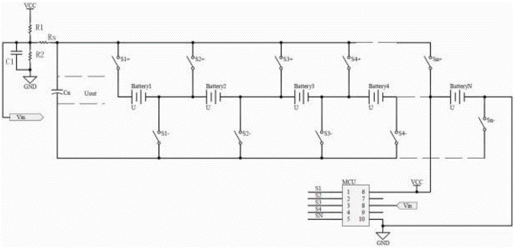
[0053] The first end of each positive pole switch is connected to the positive pole of a single battery, and the second end is respectively connected to one end of the output capacitor and a control terminal of the control center; the first end of each negative pole switch is connected to a single battery connected to the negative pole of the output capacitor, and the second end is respectively connected to the other end of the output capacitor and the other control end of the control center; both ends of the output capacitor are respectively connected to the first voltage output end and the second voltage output end. Further, the control center is an MCU, and the MCU receives...

Embodiment 2

[0068] see again figure 1 , the present invention also provides a battery pack step-down circuit, comprising: a battery pack composed of multiple single cells connected in series, several positive switches, several negative switches, an output capacitor Cn and a control center 100 .

[0069] The single battery BT provides power for the load circuit, the positive switch is used to control the positive output of the single battery BT, the negative switch is used to control the negative output of the single battery, and the output capacitor Cn is used to filter the ripple at the moment of switch switching. The control center 100 is used to control the closing or opening of the positive switch and the negative switch. The control center is MCU. The positive switch and the negative switch are relays or MOS tubes. The output capacitor is composed of several single capacitors connected in parallel.

[0070] The first terminal of each positive switch is connected to the positive te...


PUM


Abstract

The invention discloses a voltage reduction method and a voltage reduction circuit of a battery pack. According to the voltage reduction circuit, the first end of each positive electrode switch is connected with the positive electrode of a single battery while the second end is connected with one end of an output capacitor and a control end of a control center separately; the first end of each negative electrode switch is connected with the negative electrode of a single battery; and the two ends of the output capacitor are connected with a first voltage output end and a second voltage output end respectively. The voltage reduction method comprises the following steps of S1, calculating the number of sections of power supply single batteries in each time according to a target voltage; S2, determining switch combinations according to the number of sections of the power supply single batteries, and closing a switch combination; S3, determining the value of a load current, and calculating power supply time according to the value of the load current; S4, after passing the power supply time, disconnecting the current switch combination, and closing the next switch combination; and S5, repeatedly executing the step S3, realizing alternate closing of each switch combination, and outputting the target voltage. By adoption of the voltage reduction method and the voltage reduction circuit, conversion loss can be lowered, and interference generated by a switching circuit can be lowered.

Description

technical field [0001] The invention relates to the field of battery pack voltage drop circuits, in particular to a battery pack voltage drop method and a voltage drop circuit. Background technique [0002] With the widespread use of portable devices such as automotive electronics and home energy storage, the use of battery packs has become more and more extensive, and using battery packs for power supply has become a trend. Since the power and voltage requirements of the electrical equipment and the battery pack's own control circuit are different, it is necessary to set a conversion circuit in the circuit to convert the voltage of the battery pack into the voltage required by the electrical equipment, such as: switch control relay, etc. Moreover, the more switches, the greater the converted current, and the greater the loss of the conversion circuit. [0003] At present, the power supply circuit of the battery pack mainly reduces the loss caused by the large current by re...

Claims


Application Information

Patent Timeline
Patent Type & Authority Applications(China)
IPC IPC(8): H01M10/42
CPCH01M10/4207H01M10/425Y02E60/10
Inventor 王延聪
Owner HUIZHOU BNET TECH CO LTD
Why Eureka
Try Eureka