
An rc-igbt device with integrated body diode at junction terminal controlled by mosfet

A junction terminal and diode technology, applied in the field of semiconductor power devices, can solve problems such as low chip utilization and uneven current distribution, achieve soft reverse recovery characteristics, reduce forward conduction voltage drop, and improve overall performance.

Active Publication Date: 2019-09-03
杨利华
View PDF4 Cites 0 Cited by
  • Summary
  • Abstract
  • Description
  • Claims
  • Application Information

AI Technical Summary

Problems solved by technology

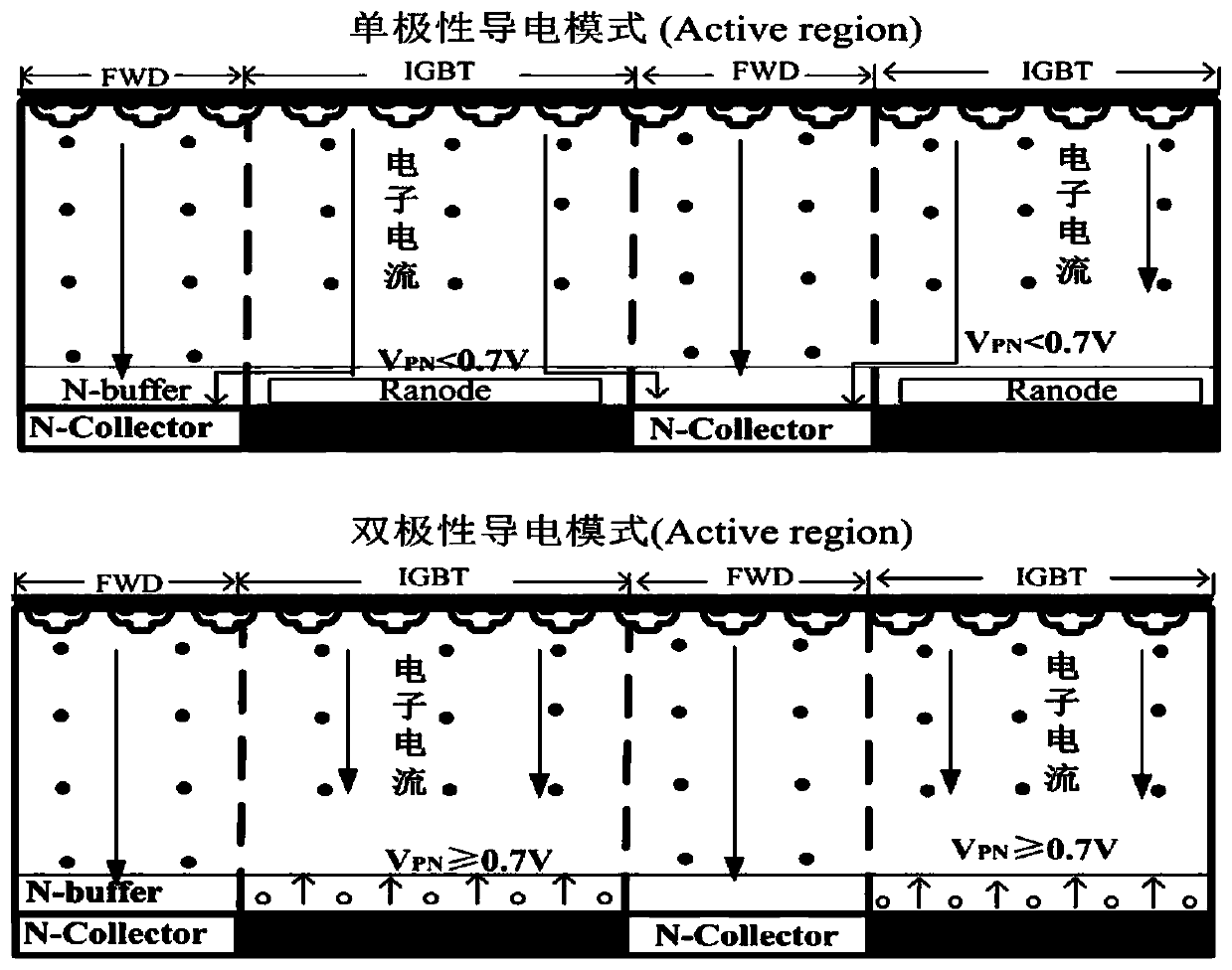
[0003] However, the traditional RC-IGBT has some shortcomings of its own: on the one hand, due to the introduction of the N-Collector, the electrons flowing out from the MOS flow to the N-Collector with a low barrier first when flowing to the collector, and the PN junction at the bottom (P- Collector / N-buffer) to generate a potential difference VPN such as figure 2 shown
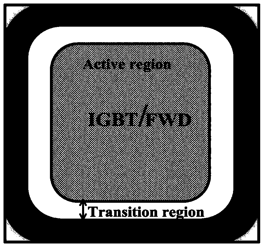
In this way, no matter whether the traditional RC-IGBT works in the IGBT forward conduction mode or the FWD reverse conduction mode, only the active region conducts current, and the junction termination region (Edgetermination) area is as large as figure 1 image 3 As shown, it only plays a role of bearing the reverse breakdown voltage, and no conduction current flows, resulting in uneven current distribution and low chip utilization.

Method used


Image

  • An rc-igbt device with integrated body diode at junction terminal controlled by mosfet
  • An rc-igbt device with integrated body diode at junction terminal controlled by mosfet
  • An rc-igbt device with integrated body diode at junction terminal controlled by mosfet

Examples

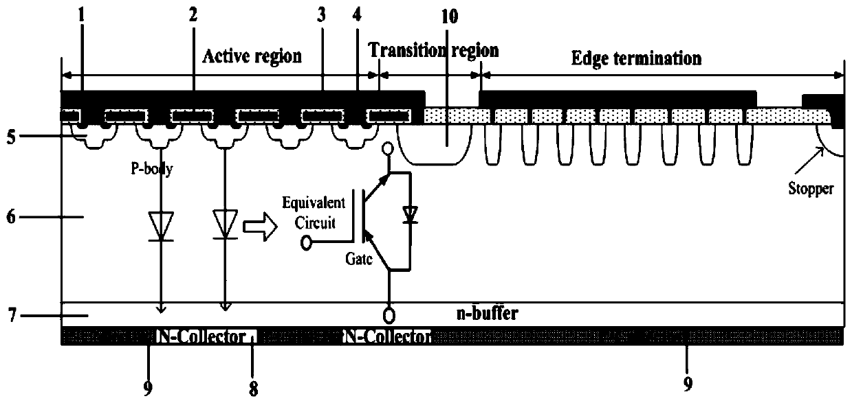

Embodiment Construction

[0024] The preferred embodiments of the present invention will be described in detail below with reference to the accompanying drawings.

[0025]The present invention proposes an RC-IGBT device that integrates a body diode through a MOSFET control junction terminal, and its structure is as follows Figure 4 As shown, the layout of the layout is as follows Figure 5 shown.

[0026] RC-IGBT device, including a cathode layer arranged from top to bottom, an N-drift region 6, an N buffer layer 7 and a collector region, and the collector region includes an N collector region 8 and a P collector region arranged in the same layer 9. Several polysilicon gate electrodes 2 are arranged at intervals in the cathode layer, an active emitter 4 is formed between two adjacent polysilicon gate electrodes, and each polysilicon gate electrode is covered with SiO 2 Surrounded by the gate oxide layer 3; a P-body region 5 is arranged below each active emitter, and the P-body region 5 is located on...


PUM


Abstract

The invention relates to an RC-IGBT and belongs to the field of semiconductor power devices. The RC-IGBT comprises a cathode layer, an N-drift region, an N-buffer layer and a collector region which are disposed from top to bottom. The collector region comprises an N collector region and a P collector region which are disposed in the same layer. A plurality of polysilicon gate electrodes are arranged in the cathode layer at intervals. Each gate electrode is surrounded by a SiO2 silicon gate oxide layer. The RC-IGBT device comprises, from left to right, an active region, a transition region and an edge termination region. The bottom layer of the edge termination region is completely constituted by the N collector region. The edge termination region integrates a body diode. The field limiting ring P-ring of the edge termination is used as the anode of the diode, the N collector region of the bottom layer of the edge termination region is used as the cathode of the diode. The on-off state of the diode is controlled by a MOSFET integrated into the transition region. The RC-IGBT device can completely eliminate a snapback phenomenon in a forward on-state IGBT mode, and reduces forward on-state voltage drop by 19.4%. Such structure greatly improves the performance of the RC-IGBT.

Description

technical field [0001] The invention relates to the field of semiconductor power devices, in particular to an RC-IGBT device with a junction terminal integrated body diode controlled by a MOSFET. Background technique [0002] IGBT (Insulated Gate Bipolar Transistor, Insulated Gate Bipolar Transistor) is widely used in high-speed rail, new energy development, household appliances, smart grid and other fields because of its withstand voltage rating from 600V to 6500V. However, the IGBT is a unidirectional conduction device, which is equivalent to two back-to-back diodes and cannot be conducted in reverse conduction. In the application of a typical IGBT inverter circuit, it is necessary to connect a free wheeling diode FWD (Free Wheeling Diode) in antiparallel for protection. RC-IGBT (Reverse-Conducting Insulated Gate Bipolar Transistor, Reverse Conducting Insulated Gate Bipolar Transistor) replaces part of the collector P-Collector of the IGBT with N-Collector, and the collec...

Claims


Application Information

Patent Timeline
Patent Type & Authority Patents(China)
IPC IPC(8): H01L29/417H01L29/423H01L29/66H01L29/739
Inventor 陈伟中郭乔贺利军黄义
Owner 杨利华
Learn More