High Dynamic Range Image Imaging Method Based on 3D Digital Microscopic Imaging System
A high dynamic range, digital microscopy technology, used in microscopy, image analysis, image enhancement, etc., can solve the problem of inability to capture high-definition dynamic scenes, overcome the inability to see reflective and non-reflective areas at the same time, and reduce computational complexity Effect
- Summary
- Abstract
- Description
- Claims
- Application Information
AI Technical Summary
Problems solved by technology
Method used
Image


Examples
Embodiment 1
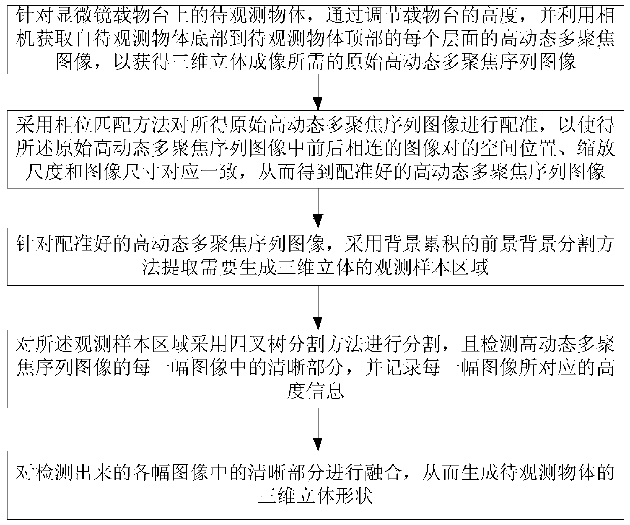
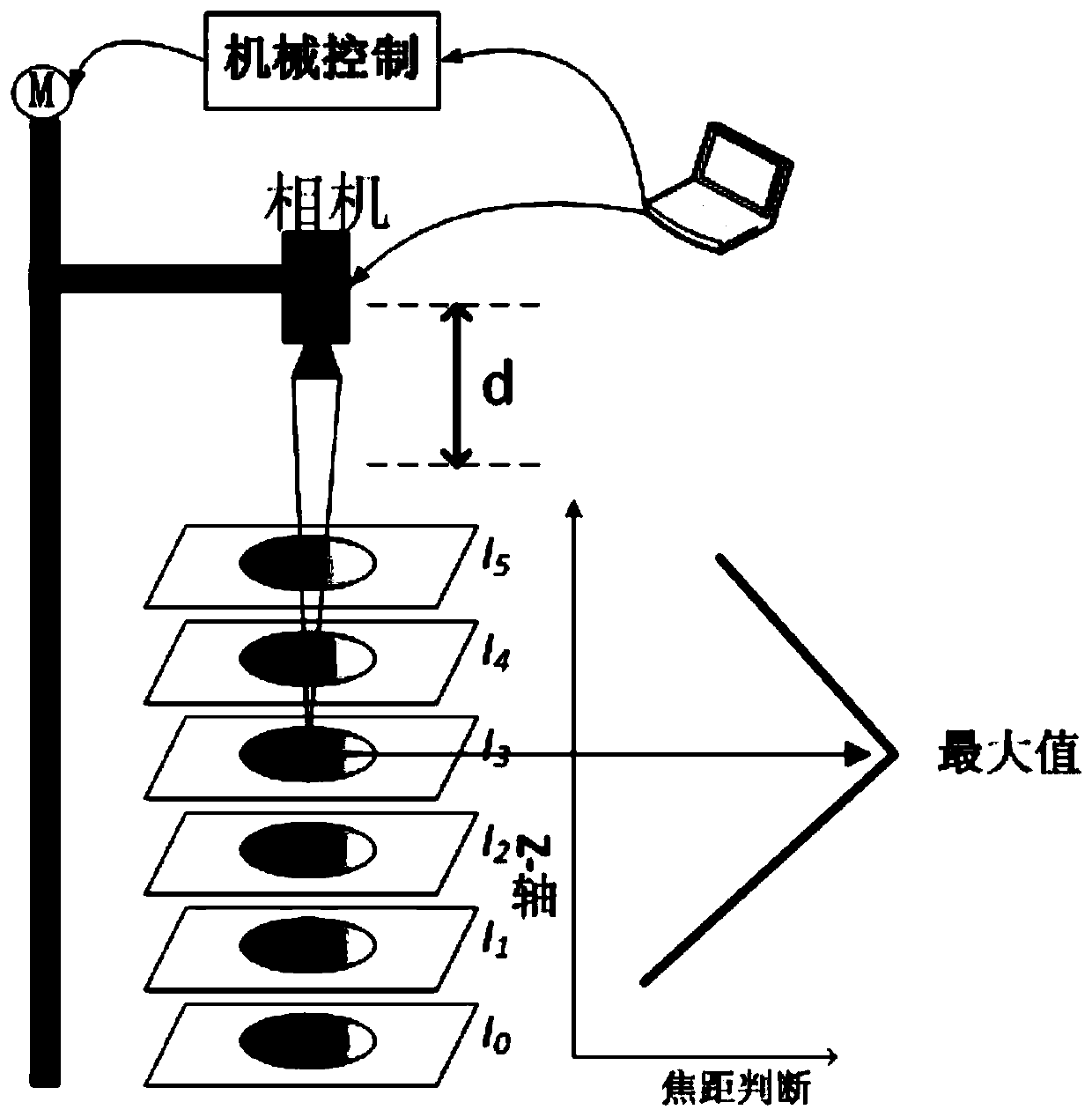
[0075] like figure 2 As shown, the 3D digital microscopic imaging system used in the first embodiment includes a traditional optical microscope, an automatic stage capable of moving in any direction of the X-axis, Y-axis and Z-axis, a CMOS camera and a computer. Wherein, the object to be observed in the first embodiment is a metal screw, and the metal screw is placed on the automatic stage. see figure 1 As shown in , the high dynamic range image imaging method based on the 3D digital microscopic imaging system in the first embodiment includes the following steps:
[0076] Step 1. For the object to be observed on the microscope stage, that is, the metal screw, by adjusting the height of the stage, the CMOS camera is focused on each layer of the object to be observed, that is, each layer of the metal screw, And use the camera to obtain high dynamic multi-focus images of each layer from the bottom of the metal screw to the top of the metal screw to obtain the original high dyn...
Embodiment 2
[0116] In the second embodiment, a plastic bank card is used as the object to be observed, and the bank card has a lowercase English letter "d". Wherein, the steps for generating the three-dimensional image of the bank card are the same as the steps for generating the three-dimensional image of the metal screw in Embodiment 1, and will not be repeated here.
[0117] In the second embodiment, in order to verify the accuracy and robustness of the high dynamic range image imaging method of the present invention, the second embodiment provides the corresponding high dynamic range image generated by the bank card. For details, see Figure 7 a~ Figure 7 shown in f. Figure 8 For the bank card in the second embodiment, the method of generating a 3D stereoscopic shape using a high dynamic range image and the square root error comparison diagram without using a high dynamic range image.
[0118] Depend on Figure 8 It can be seen that for the same focusing factor, the square root e...
Embodiment 3
[0120] In the third embodiment, a metal chip is used as the object to be observed. Wherein, the steps for generating the three-dimensional image of the metal chip are the same as the steps for generating the three-dimensional image of the metal screw in Embodiment 1, and will not be repeated here.
[0121] Figure 10 The square root error comparison diagram of the 3D stereoscopic image generated by the method of generating 3D stereoscopic shape for high dynamic range image and the method of generating 3D stereoscopic shape of original automatic exposure image.
[0122] Depend on Figure 10 It can be seen that for the same focusing factor, the square root error value of the focusing factor corresponding to the 3D stereoscopic shape generated by using the high dynamic range image is smaller than the square root error value of the focusing factor corresponding to the 3D stereoscopic shape not generated by using the high dynamic range image. It can be seen that the 3D stereoscop...
PUM
 Abstract
Description
Claims
Application Information
 - R&D
- Intellectual Property
- Life Sciences
- Materials
- Tech Scout
- Unparalleled Data Quality
- Higher Quality Content
- 60% Fewer Hallucinations
Browse by: Latest US Patents, China's latest patents, Technical Efficacy Thesaurus, Application Domain, Technology Topic, Popular Technical Reports.
© 2025 PatSnap. All rights reserved.Legal|Privacy policy|Modern Slavery Act Transparency Statement|Sitemap|About US| Contact US: help@patsnap.com