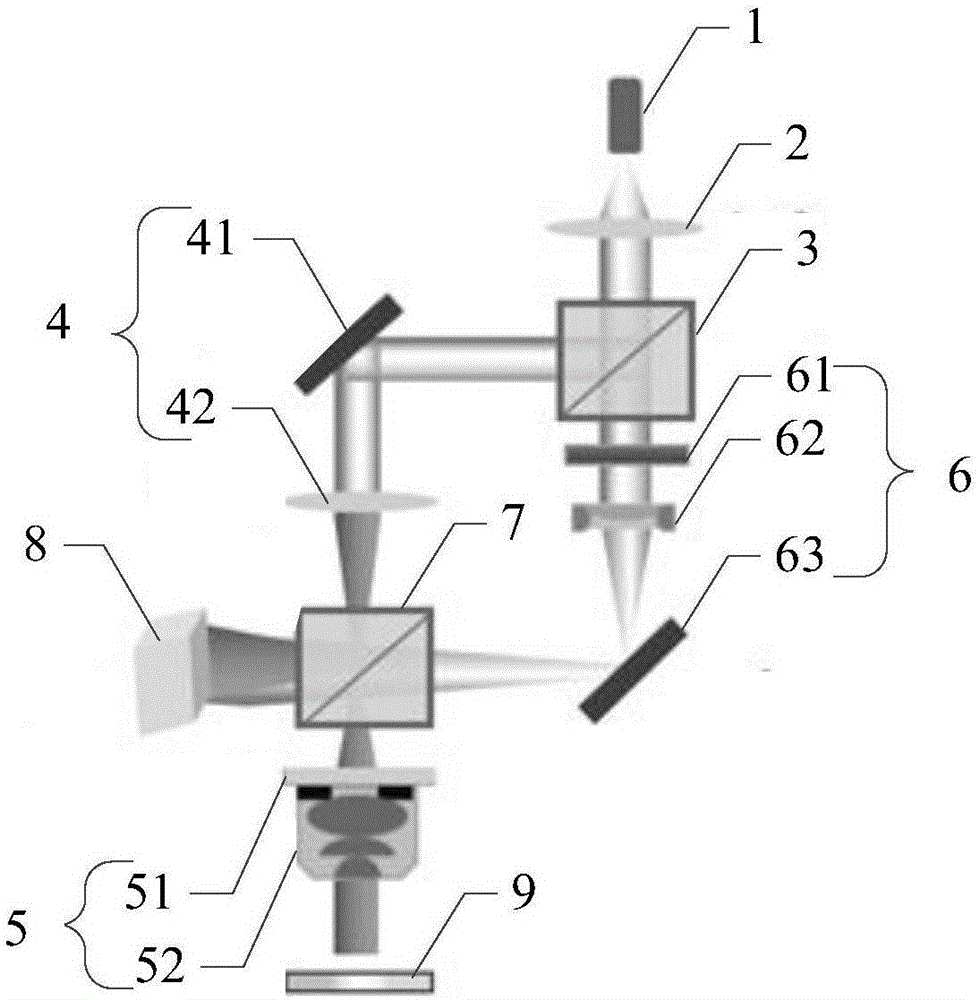
Reflection-type digital holographic microscope imaging device based on electrically controlled varifocal lens
A digital holographic microscope and imaging device technology, applied in the direction of instruments, can solve problems such as inability to guarantee system stability, achieve the effects of ensuring stability and practicability, eliminating phase distortion, and avoiding mechanical movement
- Summary
- Abstract
- Description
- Claims
- Application Information
AI Technical Summary
Problems solved by technology
Method used
Image

Examples
Embodiment Construction
[0037] In order to make the object, technical solution and advantages of the present invention clearer, the present invention will be further described in detail below in conjunction with the accompanying drawings and embodiments. It should be understood that the specific embodiments described here are only used to explain the present invention, not to limit the present invention.
[0038] The main realization idea of the present invention is: use the first beam splitter to separate the incoming laser light into object light and reference light; After the parallel light is reflected by the non-transparent sample to be tested, it enters the microscopic objective lens again, thereby forming the object light spherical wave; in the reference light path, because the electronically controlled zoom lens is introduced, the electronically controlled zoom lens can be adjusted by adjusting the current. Zoom the focal length of the lens, thereby producing the reference light spherical w...
PUM
 Abstract
Description
Claims
Application Information
 - Generate Ideas
- Intellectual Property
- Life Sciences
- Materials
- Tech Scout
- Unparalleled Data Quality
- Higher Quality Content
- 60% Fewer Hallucinations
Browse by: Latest US Patents, China's latest patents, Technical Efficacy Thesaurus, Application Domain, Technology Topic, Popular Technical Reports.
© 2025 PatSnap. All rights reserved.Legal|Privacy policy|Modern Slavery Act Transparency Statement|Sitemap|About US| Contact US: help@patsnap.com