
A three-dimensional piezoelectric driven micromirror adjustment device

A technology for driving micromirrors and adjusting devices, applied in optical components, instruments, optics, etc., can solve the problems of no relevant description, difficult to locate successfully at one time, insufficient adaptability, etc., to achieve large displacement adjustment and realize multiple degrees of freedom. Adjustable and responsive effects

Active Publication Date: 2019-06-25
NANJING UNIV OF SCI & TECH
View PDF3 Cites 0 Cited by
  • Summary
  • Abstract
  • Description
  • Claims
  • Application Information

AI Technical Summary

Problems solved by technology

However, the traditional micromirror adjustment mechanism generally adopts mechanical transmission such as precision screw pair, rolling guide rail, turbine-concave mechanism, etc., and there are errors such as friction and clearance, so it is difficult to successfully locate at one time.
There are also defects such as insufficient adaptability to electric heating, electromagnetic and other driving forms.
Therefore, there is an urgent need for a micromirror adjustment device with simple structure, miniaturization and adaptability to various occasions, but there is no relevant description in the prior art.

Method used


Image

  • A three-dimensional piezoelectric driven micromirror adjustment device
  • A three-dimensional piezoelectric driven micromirror adjustment device
  • A three-dimensional piezoelectric driven micromirror adjustment device

Examples


Embodiment

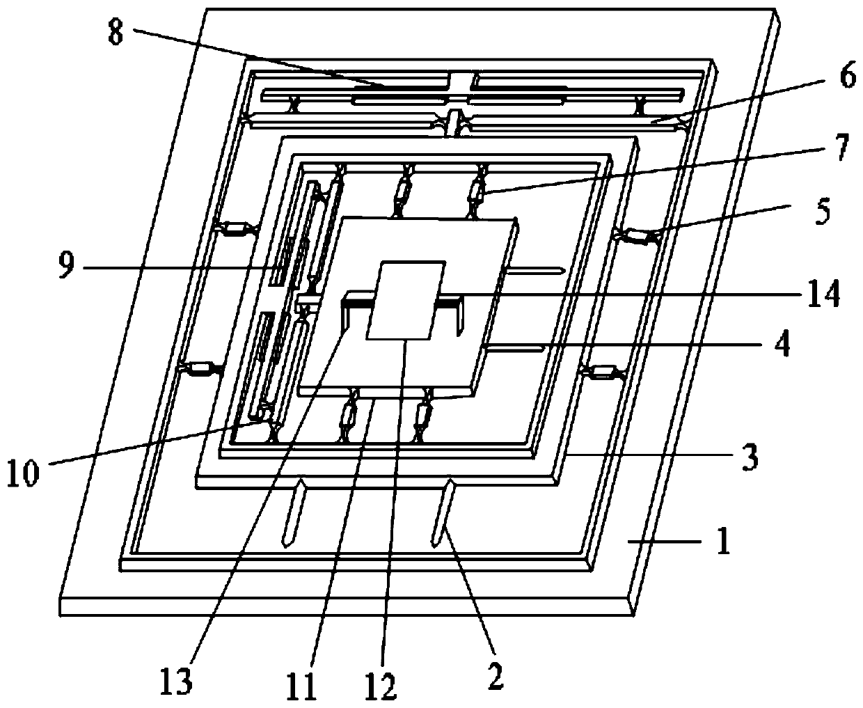
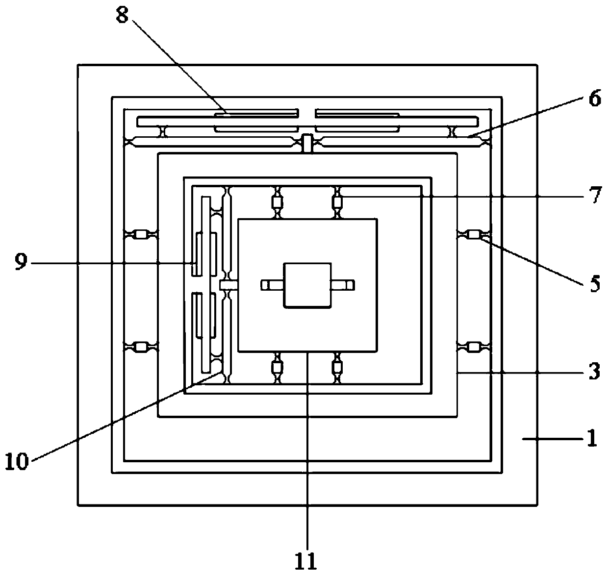
[0029] combine figure 1 , a three-dimensional piezoelectric drive micromirror adjustment device of the present invention includes an X-direction displacement adjustment platform, a Y-direction displacement adjustment platform, a Z-direction displacement adjustment mechanism, an X-direction piezoelectric film driver, a Y-direction piezoelectric film driver, and a Z-direction Piezoelectric film drivers, micromirrors, etc. The X-direction displacement adjustment includes an X-direction displacement amplification mechanism 10 , an X-direction flexible hinge guide mechanism 7 , an X-direction displacement adjustment platform 11 , and an X-direction piezoelectric film driver 9 symmetrically arranged about the central axis of the Y-direction displacement adjustment platform 3 in the X direction. The Y-direction displacement adjustment includes a Y-direction displacement amplification mechanism 6 , a Y-direction flexible hinge guide mechanism 5 , a Y-direction displacement adjustment ...


PUM


Abstract

The invention discloses a three-dimensional piezoelectric-driving micromirror adjusting device. The device comprises a coarse moving platform, an X-direction displacement adjusting platform, a Y-direction displacement adjusting platform, a Z-direction displacement adjusting platform, pulley guide rail mechanisms, piezoelectric films and flexible hinges. The coarse moving platform, the X-direction displacement adjusting platform and the Y-direction displacement adjusting platform are overlapped through the pulley guide rail mechanisms, and the Z-direction displacement adjusting platform is located over the X-direction displacement adjusting platform. After the coarse moving platform is positioned, a voltage is applied to the Y-direction piezoelectric film, and under the inverse piezoelectric action, the Y-direction piezoelectric film enables cantilever beams at the two ends to generate output displacement and pushes the Y-direction displacement adjusting platform to conduct Y-direction displacement adjusting through a displacement amplification mechanism; in the same way, the X-direction piezoelectric film pushes the X-direction displacement adjusting platform to conduct X-direction displacement adjusting, and the Z-direction piezoelectric film pushes the X-direction displacement adjusting platform to conduct Z-direction displacement adjusting. The three-dimensional piezoelectric-driving micromirror adjusting device is simple and compact in structure, capable of achieving multi-degree-of-freedom adjusting, high in response speed and suitable for multiple scenes.

Description

technical field [0001] The invention relates to a driving device, in particular to a three-dimensional piezoelectric driving micromirror adjusting device. Background technique [0002] In recent years, more and more attention has been paid to the application research of microelectromechanical systems (MEMS) in the field of optics. Its application has been extended to medicine, military and other industries. Due to its low inertia, it can be positioned precisely. At present, MEMS has become the focus of research all over the world. [0003] Micromirrors are one of the typical representatives. Recently, many research institutes have proposed different types of micromirrors and their driving mechanisms. However, the traditional micromirror adjustment mechanism generally adopts mechanical transmission such as precision screw pair, rolling guide rail, and turbine-cam gear mechanism. There are errors such as friction and clearance, and it is difficult to locate successfully at ...

Claims


Application Information

Patent Timeline
Patent Type & Authority Patents(China)
IPC IPC(8): G02B26/08
CPCG02B26/0858
Inventor 王新杰刘亚风王炅
Owner NANJING UNIV OF SCI & TECH
Learn More