
Hydraulic sandwich valve

A splint valve and splint technology, used in sliding valves, valve devices, engine components, etc., can solve the problems of reduced opening and closing precision of the valve body, failure to achieve the purpose of adjustment, reduced adjustment effect, etc., and achieve high sealing safety. , High precision and stable structure

Inactive Publication Date: 2017-06-13
天津惠博普管道技术有限公司
View PDF5 Cites 0 Cited by
  • Summary
  • Abstract
  • Description
  • Claims
  • Application Information

AI Technical Summary

Problems solved by technology

[0004] Existing splint valves are prone to structural deformation due to the impact of moving fluid for a long time, and the precision of opening and closing of the valve body is easily reduced due to damage, so that the adjustment effect is reduced or the expected adjustment purpose cannot be achieved.

Method used


Image

  • Hydraulic sandwich valve
  • Hydraulic sandwich valve

Examples


Embodiment Construction

[0024] It should be noted that, in the case of no conflict, the embodiments of the present invention and the features in the embodiments can be combined with each other.

[0025] In describing the present invention, it should be understood that the terms "center", "longitudinal", "transverse", "upper", "lower", "front", "rear", "left", "right", The orientations or positional relationships indicated by "vertical", "horizontal", "top", "bottom", "inner", "outer", etc. are based on the orientation or positional relationships shown in the drawings, and are only for the convenience of describing the present invention Creation and simplification of description, rather than indicating or implying that the device or element referred to must have a specific orientation, be constructed and operate in a specific orientation, and therefore should not be construed as limiting the invention. In addition, the terms "first", "second", etc. are used for descriptive purposes only, and should no...


PUM


Abstract

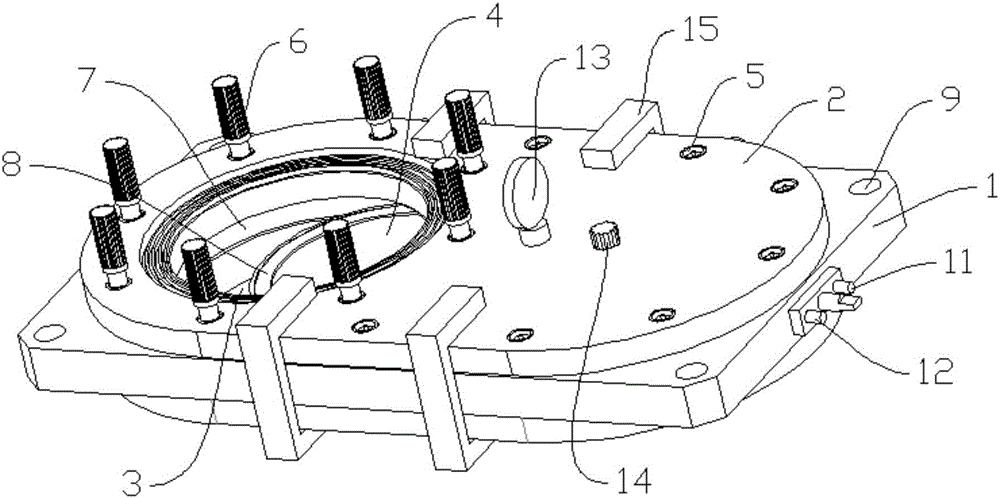
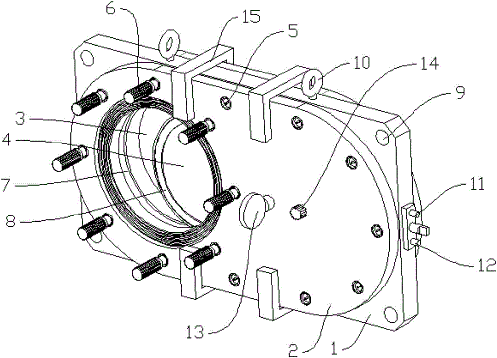
The invention provides a hydraulic splint valve, which includes a central splint body and side splint bodies symmetrically arranged on both sides of the central splint body. The inside of the central splint body is a hollow structure. One side of the face is provided with a fluid passage for the fluid to pass through, and a movable plate capable of opening or closing the fluid passage is provided inside the central splint body, and the movable plate passes through the hydraulic pressure provided on one side of the central splint body. drive mechanism movement.

Description

technical field [0001] The invention belongs to the technical field of valves, and in particular relates to a valve control component used in a delivery system. Background technique [0002] The valve is one of the commonly used control components in the fluid delivery system. During the delivery of fluid (such as gas, liquid, etc.), it often plays the role of throttling, shunting, pressure stabilization, and pressure relief. It is to maintain the stability of the fluid delivery system. One of the important parts of operation. [0003] The splint valve is a commonly used valve component. It is usually set in the center of the pipeline through which the fluid flows and is perpendicular to the direction of fluid delivery. to regulate flow. [0004] Due to the impact of moving fluid for a long time, the existing splint valve is likely to cause structural deformation, and the precision of opening and closing of the valve body is easily reduced due to damage, so that the adjust...

Claims


Application Information

Patent Timeline
Patent Type & Authority Applications(China)
IPC IPC(8): F16K3/02F16K3/30
CPCF16K3/0281F16K3/30
Inventor 苏涛乔昊
Owner 天津惠博普管道技术有限公司
Learn More