Battery box pressure relief device

A technology of pressure relief device and battery box, which is applied in the direction of secondary battery, exhaust plug device, battery and its environment isolation, etc. It can solve the problems of inconvenient operation, battery damage, battery box pressure relief, etc., and achieves simple structure and convenient installation , Reliable effect of pressure relief

Active Publication Date: 2021-04-06
JIANGSU TUOMILUO ENVIRONMENTAL TEST EQUIP CO LTD
View PDF9 Cites 0 Cited by
  • Summary
  • Abstract
  • Description
  • Claims
  • Application Information

AI Technical Summary

Problems solved by technology

[0002] The battery environment test needs to be carried out in the battery box. During the test, the battery may be damaged, leaked, swelled, caught fire, exploded, etc.; when the above situations occur, the pressure in the battery environment battery box will increase, resulting in The danger of explosion of the battery box may even lead to personal injury and property loss. Therefore, it is necessary to release the pressure of the battery box in time
Common battery box pressure relief devices generally use torsion springs to turn over and seal and release pressure or use electric devices to release pressure, which is inconvenient to operate, the force on the pressure relief hole is uneven, and the pressure relief pressure is difficult to control. The pressure relief operation can not achieve the effect of effectively protecting the battery box; moreover, the common pressure relief devices on the market are also prone to external shocks during the pressure relief process, causing harm to the surrounding environment and operators, and are relatively safe. Low; in addition, the structure of the electric pressure relief device is complex and the cost is high. Once the pressure is released, it will cause damage and the cost will be high

Method used


Image

  • Battery box pressure relief device
  • Battery box pressure relief device

Examples


Embodiment Construction

[0027] The present invention will be described in further detail below in conjunction with the accompanying drawings and embodiments. It should be understood that the specific embodiments described here are only used to explain the present invention, but not to limit the present invention. In addition, it should be noted that, for the convenience of description, only some structures related to the present invention are shown in the drawings but not all structures.

[0028] In the description of the present invention, unless otherwise clearly specified and limited, the terms "connected", "connected" and "fixed" should be understood in a broad sense, for example, it can be a fixed connection, a detachable connection, or an integrated ; It can be a mechanical connection or an electrical connection; it can be a direct connection or an indirect connection through an intermediary, and it can be the internal communication of two components or the interaction relationship between two ...


PUM


Abstract

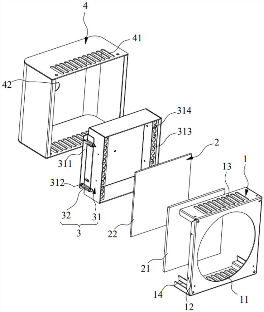
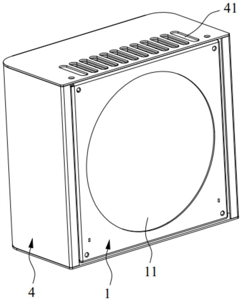
The invention belongs to the technical field of battery environment tests, and particularly relates to a battery box pressure relief device which comprises a fixed frame, a sealing assembly, a pressure relief assembly and a protective cover. The fixed frame is fixed on a battery box and is provided with a pressure relief hole which communicates with the battery box; one face of the sealing assembly abuts against the fixed frame and covers the pressure relief hole; the pressure relief assembly comprises a pressure relief cover and a plurality of elastic pressure relief pieces, one end of each elastic pressure relief piece is connected with the pressure relief cover, the other end of each elastic pressure relief piece is connected with the fixed frame, and the elastic pressure relief pieces are configured to enable the pressure relief cover to abut against the fixed frame through elastic pre-tightening force; the other face of the sealing assembly abuts against the pressure relief cover; and the protective cover is fixedly connected with the fixed frame, a protective cavity is formed in the protective cover, and the pressure relief assembly is located in the protective cavity. According to the battery box pressure relief device, the pressure relief pressure is accurately controlled through the pre-tightening force of the elastic pressure relief piece, the pressure relief hole is stressed uniformly, the structure is simple, and the cost is low; and the pressure relief assembly is located in the protective cover, safety is high, and damage to the surrounding environment and operators in the pressure relief process is avoided.

Description

technical field [0001] The invention relates to the technical field of battery environmental testing, in particular to a pressure relief device for a battery box. Background technique [0002] The battery environment test needs to be carried out in the battery box. During the test, the battery may be damaged, leaked, swelled, caught fire, exploded, etc.; when the above situations occur, the pressure in the battery environment battery box will increase, resulting in The danger of battery box explosion may even cause personal injury and property loss. Therefore, it is necessary to release the pressure of the battery box in time. Common battery box pressure relief devices generally use torsion springs to turn over and seal and release pressure or use electric devices to release pressure, which is inconvenient to operate, the force on the pressure relief hole is uneven, and the pressure relief pressure is difficult to control. The pressure relief operation can not achieve the e...

Claims


Application Information

Patent Timeline
Patent Type & Authority Applications(China)
IPC IPC(8): H01M50/30H01M50/24H01M10/613H01M10/655H01M10/658
CPCH01M10/613H01M10/655H01M10/658Y02E60/10
Inventor 赵源汤耀明李永兵
Owner JIANGSU TUOMILUO ENVIRONMENTAL TEST EQUIP CO LTD
Why Eureka
Try Eureka