
Assembly type precast light floor

A prefabricated and floor-slab technology, applied to floors, building components, buildings, etc., can solve problems such as low construction efficiency, poor concrete adhesion, and difficulty in ensuring overall performance

Inactive Publication Date: 2017-06-13
BEIJING UNIV OF TECH
View PDF6 Cites 8 Cited by
  • Summary
  • Abstract
  • Description
  • Claims
  • Application Information

AI Technical Summary

Problems solved by technology

Although the cast-in-place reinforced concrete floor has the advantages of good integrity and high rigidity, it requires formwork support, a large amount of wet work on site, low construction efficiency, and a long construction period. Support formwork is required, but the cost is high, and the profiled steel plate needs to be treated with fire protection, and its adhesion to concrete is poor, and the bottom surface is uneven, so it often needs to be treated as a suspended ceiling; The above application has its outstanding advantages, but the existing laminated panels have the following disadvantages: the laminated surface between the prefabricated layer and the laminated layer needs to be strictly treated, and the overall performance after laminated is difficult to guarantee; the thermal insulation of laminated panels Difficult to guarantee thermal performance; on-site steel bar binding is cumbersome and construction speed is slow

Method used


Image

  • Assembly type precast light floor
  • Assembly type precast light floor
  • Assembly type precast light floor

Examples


Embodiment Construction

[0021] The present invention will be described in detail below in conjunction with the accompanying drawings. The embodiments described below with reference to the accompanying drawings are examples and are intended to explain the present invention, but should not be construed as limiting the present invention.

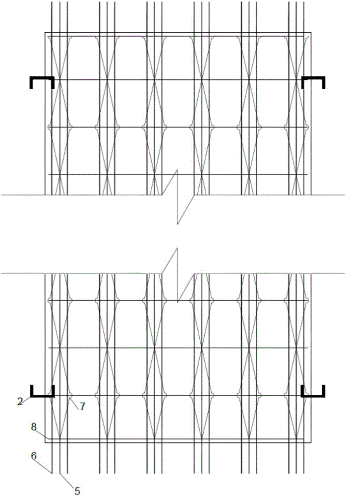
[0022] as attached figure 1 - attached Figure 4 As shown, the present invention is completed in one pouring in the factory. In the factory, the upper chord steel bar (5), the lower chord steel bar (6) and the obliquely bent steel bar (7) are welded to form a steel bar truss (4), and the connecting channel steel (2) is welded and connected with the upper and lower horizontally distributed steel bars (8), and then the light weight is completed. Firstly, the precast concrete layer (1) and the lower part of the concrete are poured first. When it is not yet solidified, the lightweight material plate (3) is fixed in the middle of the steel truss (4), and then horizontally ...


PUM


Abstract

The invention provides an assembly type precast light floor. The assembly type prefabricating light floor comprises a precast concrete layer, connection channel steel, a light material plate, a steel bar truss, an upper chord steel bar, a lower chord steel bar, a slant bending steel bar and a horizontal distribution steel bar. Manufacturing of the steel bar truss and the light material plate is finished firstly in a factory, and the connection channel steel and the horizontal distribution steel bar are welded; when lower part concrete of the precast concrete layer is not yet subjected to curing molding, the light material plate is fixedly placed in the middle of the steel bar truss, then the horizontal distribution steel bar is placed in the middle of the steel bar truss in the total length, the steel bar truss is connected with the upper chord steel bar in a bound mode, and then upper part concrete is poured on the precast concrete layer, so that manufacturing of the assembly type precast light floor is completed; in a construction field, by preburying the connection channel steel in the floor, single floors are connected into one. The assembly type precast light floor fully achieves assemblage, is in accordance with the industrialized development trend of buildings, is completed by pouring in a factory at one time, and has the advantages of being less in wet work amount, convenient to construct, high in crush resistance, high in production efficiency and the like.

Description

technical field [0001] The invention relates to an assembled prefabricated lightweight floor slab, which belongs to the field of building components. Background technique [0002] As an important horizontal component and the only horizontal support in the building structure, the floor slab has a great impact on the safety, cost and construction period of the project. At present, the floor system forms mainly include cast-in-place reinforced concrete slabs, profiled steel plate-concrete composite slabs, and laminated slabs. Although the cast-in-place reinforced concrete floor has the advantages of good integrity and high rigidity, it requires formwork support, a large amount of wet work on site, low construction efficiency, and a long construction period. Support formwork is required, but the cost is high, and the profiled steel plate needs to be treated with fire protection, and its adhesion to concrete is poor, and the bottom surface is uneven, so it often needs to be trea...

Claims


Application Information

Patent Timeline
IPC IPC(8): E04C2/288E04B5/02
CPCE04C2/2885E04B5/023E04C2/50
Inventor 刘学春徐路白正仙崔小雄商子轩
Owner BEIJING UNIV OF TECH
Learn More