
Ceramic firing method

A technology of ceramics and ceramic blanks, which is applied in the field of ceramic manufacturing, can solve problems such as poor load-bearing capacity, low mud plate strength, deformation, etc., and achieve the effects of improving firing pass rate, solving deformation problems, and reducing costs

Active Publication Date: 2017-06-13
LIXIL AS SANITARY MFG (SHANGHAI) CO LTD
View PDF4 Cites 6 Cited by
  • Summary
  • Abstract
  • Description
  • Claims
  • Application Information

AI Technical Summary

Problems solved by technology

However, due to the low strength and poor load-bearing capacity of the clay board, it is easy to break during the firing process.
After the clay board 5 breaks, the green body product 3 is deformed from the broken part A of the mud board 5 (see Image 6 (a) and Image 6 (b)), and burnt clay panels cannot be recycled

Method used


Image

  • Ceramic firing method
  • Ceramic firing method
  • Ceramic firing method

Examples


Embodiment 1

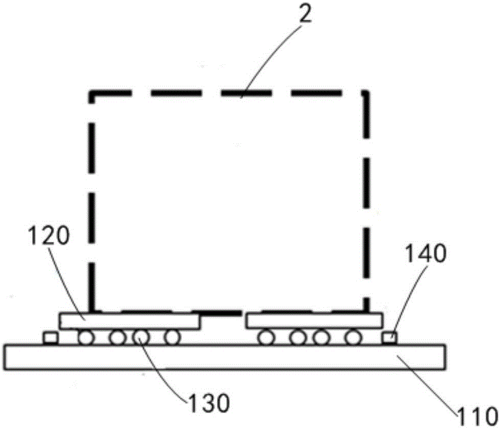
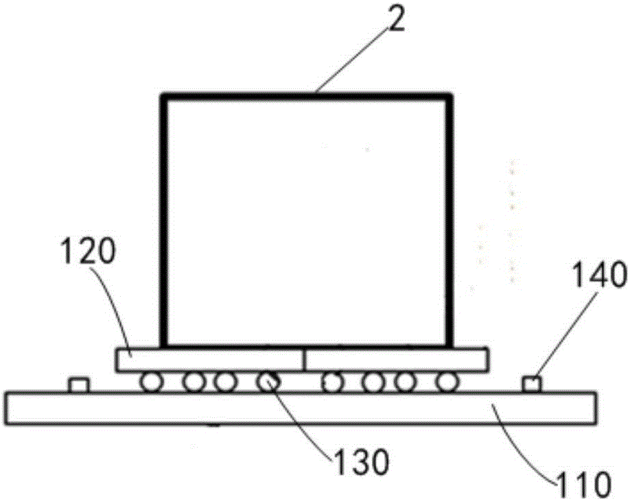
[0045] A ceramic firing method, comprising:

[0046] 1. Install the first kiln panel 110 horizontally in the kiln.

[0047] 2. A plurality of high temperature resistant ceramic balls 130 are laid on the first kiln plate 110 .

[0048] 3. Lay two second kiln panels 120 on a plurality of high-temperature-resistant ceramic balls 130, and the gap between adjacent second kiln panels is 35 mm.

[0049] 3. Place the ceramic green body 2 on the second kiln board 120 so that the bottom is evenly supported by the two second kiln boards 120 .

[0050] 4. On the first kiln plate 110, a stop frame 140 for limiting the position outside the high-temperature-resistant ceramic ball 130 is provided, and its thickness is 15 mm.

[0051] 5. Start the kiln to fire the ceramic green body 2 at a firing temperature of 1300° C. for 8 hours.

[0052] The ceramic green body fired in this embodiment is in the shape of a pair of long strips, and the shrinkage of the narrower side can be ignored, so two...

Embodiment 2

[0054] A ceramic firing method, comprising:

[0055] 1. Install the first kiln panel 110 horizontally in the kiln.

[0056] 2. Lay a plurality of high temperature resistant alumina balls 130 on the first kiln plate 110 .

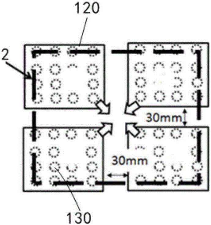
[0057] 3. Lay four second kiln panels 120 in a 2×2 matrix on multiple high-temperature-resistant alumina balls 130, and the gap between adjacent second kiln panels is 30mm.

[0058] 3. Place the ceramic green body 2 on the second kiln board 120 so that the bottom thereof is evenly supported by four second kiln boards 120 .

[0059] 4. On the first kiln plate 110, a stop frame 140 for limiting the position outside the high-temperature-resistant alumina ball 130 is provided, and its thickness is 16mm.

[0060] 5. Start the kiln to fire the ceramic green body 2 at a firing temperature of 1200° C. for 7 hours.

[0061] The ceramic body fired in this embodiment has a regular shape with almost the same length and width, so four second kiln plates 120 are select...


PUM


Abstract

A ceramic firing method includes the steps: a first kiln plate is horizontally arranged in a kiln; a plurality of high-temperature-resistant balls are laid on the first kiln plate; at least two second kiln plates for uniformly supporting at the bottom of a ceramic green body are laid on the plurality of high-temperature-resistant balls, and a gap exists between each adjacent second kiln plates; the ceramic green body is placed on the second kiln plates, and the bottom of the ceramic green body is uniformly supported by the at least two second kiln plates; and the kiln is started up for firing the ceramic green body with the firing temperature of 1100-1300 DEG C for 6-8 hours. According to the method, in the process of firing the ceramic green body, the second kiln plates can relatively move along with the green body shrinkage stress traction, so that the shrinkage stress of the product is released, the deformation problem of a high-end straight-edge product is completely solved, the firing qualified rate of the product is improved, the quality of the product is improved, and the costs are reduced.

Description

technical field [0001] The invention relates to ceramic manufacturing technology, in particular to a ceramic firing method. Background technique [0002] Due to the particularity of the firing process of the existing ceramic green body products, the final product needs to be fired at high temperature. During the firing process, the green body product 3 will shrink by about 10%, and the kiln furniture used to support the product It does not shrink, so the surface of the green body product 3 in contact with the kiln furniture 4 has a shrinkage difference, and shrinkage stress is generated to cause deformation of the contact surface of the product (see Figure 5 (a) and Figure 5 (b)), become burnt waste. [0003] Existing factory adopts the mode that spreads clay board 5 pads and burns on kiln furniture 4 for solving this type of shrinkage deformation. However, due to the low strength and poor load-bearing capacity of the clay board, it is easy to break during the firing proc...

Claims


Application Information

Patent Timeline
IPC IPC(8): C04B35/64F27D5/00
CPCC04B35/64F27D5/00
Inventor 谢生林倪永林
Owner LIXIL AS SANITARY MFG (SHANGHAI) CO LTD
Learn More