Application method for vehicle optical transmitter and receiver
A technology of optical transceiver and optical receiver, which is applied in the direction of adapting to optical transmission, such as TV system, TV, cable transmission, etc. It can solve the problems of easy distortion of data transmission, achieve the effect of small impedance, fast response speed, and ensure safe use
- Summary
- Abstract
- Description
- Claims
- Application Information
AI Technical Summary
Problems solved by technology
Method used
Image

Examples
Embodiment 1
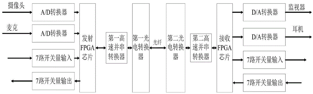
[0019] like figure 1 As shown, the first front-end camera of the present invention carries out high-resolution digitalization of multiple channels of video, audio and data through the audio and video transmitting module of the optical transceiver to form a high-speed digital stream, and then under the action of the transmitting FPGA chip, the multi-channel digital stream Perform multiplexing, quickly pass through the first photoelectric converter, convert the electrical signal into an optical signal, and transmit it to the audio and video receiving module of the optical receiver through the optical fiber; the audio and video receiving module receives the signal and demultiplexes it through the receiving FPGA chip , back to various digital signals, and finally back to analog video, audio and data.
[0020] The optical transceiver includes an optical transmitter and an optical receiver, and the optical transmitter is connected to the optical receiver through an optical fiber. T...
Embodiment 2
[0022] like figure 1 As shown, on the basis of Embodiment 1, the present embodiment includes a camera, a microphone, two A / D converters and a first high-speed parallel-to-serial converter, and the camera and the microphone communicate with two A / D converters respectively. The D converters are connected in sequence, the two A / D converters are respectively connected with the transmitting FPGA chip, and the first high-speed parallel-serial converter is connected with the FPGA chip and the first photoelectric converter. The image information or data captured by the multi-channel camera passes through the main amplifier to process the image or data, and converts the analog signal into a digital signal through the A / D converter; when the transmitting FPGA chip multiplexes the multiple digital streams , and then under the action of the first high-speed parallel-to-serial converter, the multiple digital streams are transmitted to the first photoelectric converter, and the photoelectr...
Embodiment 3
[0025] like figure 1 As shown, this embodiment is based on Embodiment 1, the optical transmitter also includes 7 switch value input interfaces and 7 switch value output interfaces, and the optical receiver includes 7 switch value output interfaces and 7 switch value output interfaces switch input interface. In addition to multiple channels of forward and reverse video and multiple channels of bidirectional data, it also supports synchronous transmission of 7 channels of forward and 7 channels of reverse switches; the 7 channels of forward and reverse switches set by the optical receiver are respectively connected to the optical transmitter The 7-way forward and reverse switches are adapted to ensure the complete transmission of large-capacity data and image information; the optical receiver also includes 7-way switch output interfaces and 7-way switch input interfaces. The 7-way forward and reverse switches set by the optical receiver are respectively compatible with the 7-w...
PUM
 Abstract
Description
Claims
Application Information
 - R&D
- Intellectual Property
- Life Sciences
- Materials
- Tech Scout
- Unparalleled Data Quality
- Higher Quality Content
- 60% Fewer Hallucinations
Browse by: Latest US Patents, China's latest patents, Technical Efficacy Thesaurus, Application Domain, Technology Topic, Popular Technical Reports.
© 2025 PatSnap. All rights reserved.Legal|Privacy policy|Modern Slavery Act Transparency Statement|Sitemap|About US| Contact US: help@patsnap.com