
Transimpedance amplifier and receiver with adaptive control gain and large dynamic range

A large dynamic range, adaptive control technology, applied in the field of optical communication, can solve the difficulty of setting the transimpedance gain value of the transimpedance amplifier and the design of the dynamic range of the input signal, unable to detect the echo pulse signal, and reducing the sensitivity of the transimpedance amplifier, etc. problems, to avoid overloading of large input electrical signals, meet sensitivity requirements, and facilitate popularization and use.

Inactive Publication Date: 2018-03-06
ROCKET FORCE UNIV OF ENG
View PDF4 Cites 0 Cited by
  • Summary
  • Abstract
  • Description
  • Claims
  • Application Information

AI Technical Summary

Problems solved by technology

Most of the existing transimpedance gains are fixed and constant values. If the transimpedance gain of the transimpedance amplifier is too large, it can meet the sensitivity requirements of low input optical power, that is, weak current signals. However, when the input optical power is too large, the transimpedance amplifier On the other hand, if the gain value of the transimpedance amplifier is small, it can meet the overload requirement of large input optical power, but when the input optical power is small, the sensitivity of the transimpedance amplifier will be reduced, and the echo pulse signal cannot even be detected.
Therefore, it can be seen that there are design difficulties in the setting of the transimpedance gain value of the analog front-end transimpedance amplifier of the imaging lidar receiver and the dynamic range of the input signal

Method used


Image

  • Transimpedance amplifier and receiver with adaptive control gain and large dynamic range
  • Transimpedance amplifier and receiver with adaptive control gain and large dynamic range
  • Transimpedance amplifier and receiver with adaptive control gain and large dynamic range

Examples


Embodiment Construction

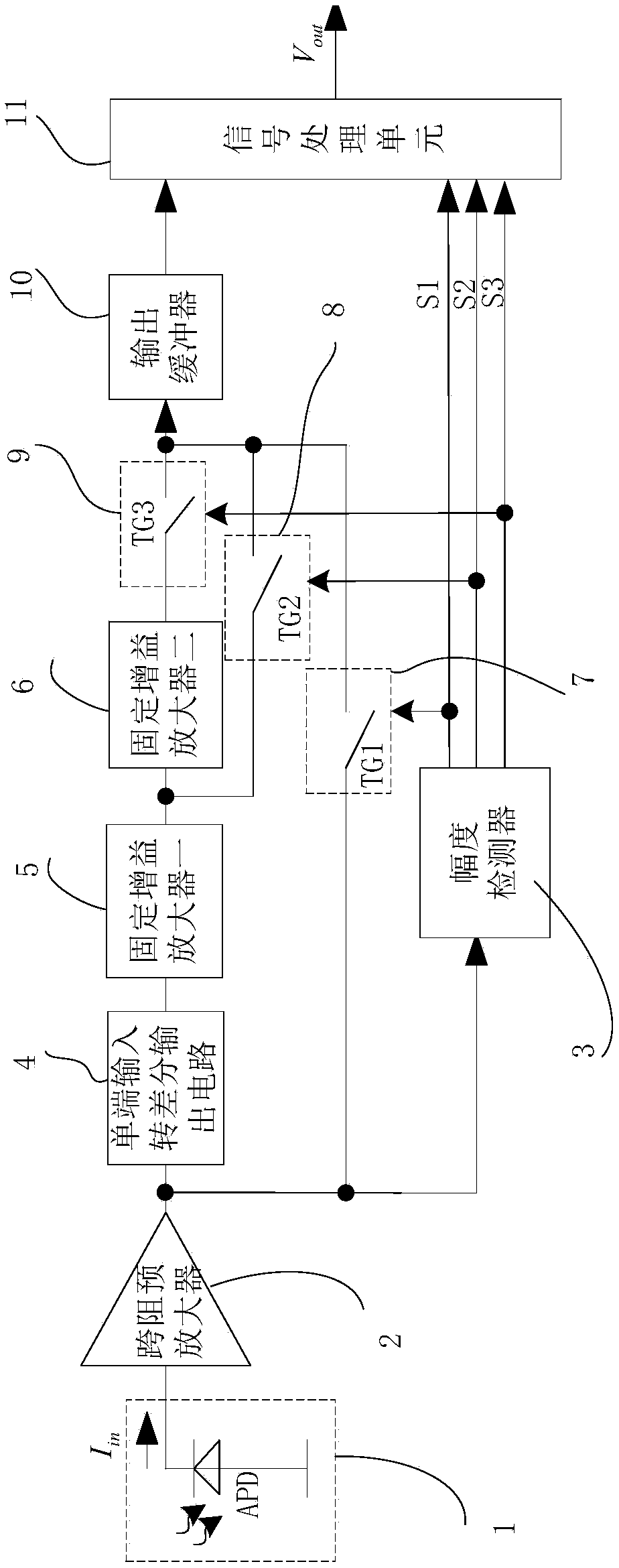
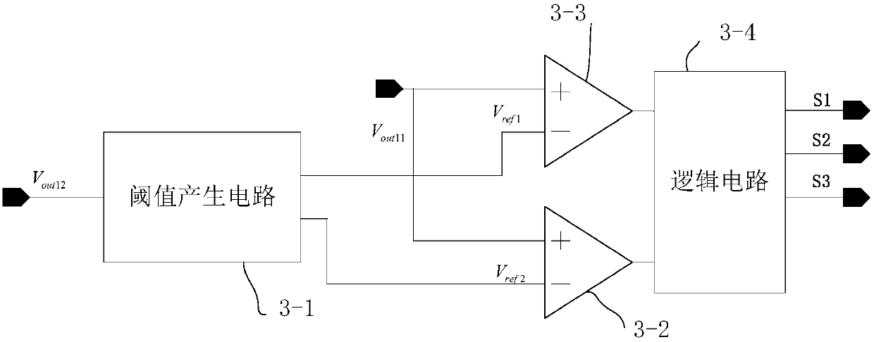
[0046] Such as figure 1 As shown, the transimpedance amplifier with adaptive control gain and large dynamic range according to the present invention includes a four-stage amplifier, an output buffer 10 and a signal processing unit 11 connected in sequence, and three sets of switches for selecting the gain amplification factor And the amplitude detector 3 connected to the signal processing unit 11 and used to control the operation of the three groups of switches, wherein,

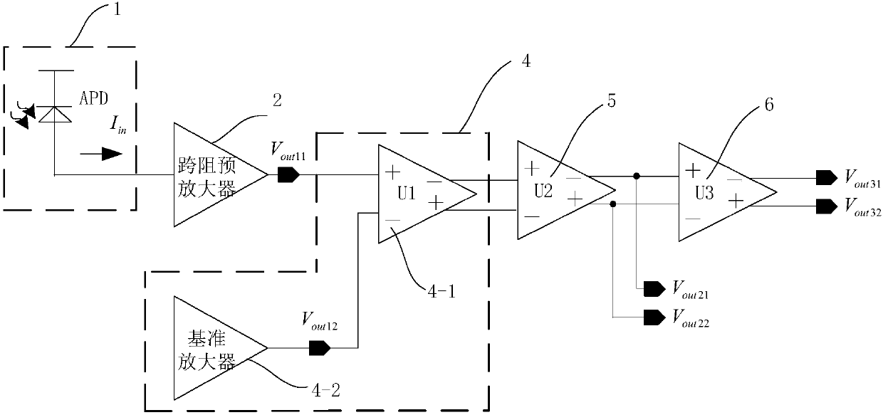
[0047] The four-stage amplifier includes a transimpedance pre-amplifier 2, a single-ended input-to-differential output circuit 4, a fixed gain amplifier 5, and a fixed gain amplifier 2 6 connected in series in order to amplify the input current signal and convert the amplified input current signal Is a voltage signal;

[0048] The output buffer 10 is used to temporarily store the voltage signal output by the four-stage amplifier;

[0049] The three groups of switches include switch group one 7, switch group two 8...


PUM


Abstract

The invention discloses a large dynamic range transimpedance amplifier with self-adaption controlling gain, which comprises a four-level amplifier, an output buffer, a signal processing unit connected in turn, three sets of switches for selecting gain amplification multiples and an amplitude detector which is connected to the signal processing unit and used forcontrolling the work of three sets of switches. The invention also discloses an optical receiver which comprises a transimpedance amplifier and a photolectric transducer module connected to the input terminal of the transimpedance prime amplifier. The invention also discloses a method for receiving and amplifying light signals which comprises the following steps: first, conversing photovoltaic; second, amplifying and processing the electrical signal by using the transimpedance amplifier, thereby the electrical signal is amplified at the first level; comparing voltage signal and selecting switch apparatus group; signal buffering and signal processing. The self-adaption control gain large dynamic range transimpedance amplifier and receiver can select the signal amplification series according to the input signal strength, which can satisfy the sensitivity requirement of the weak electrical signal and avoid the problem of overload of large input signal.

Description

Technical field [0001] The invention belongs to the technical field of optical communication, and specifically relates to a transimpedance amplifier and a receiver with adaptive control gain and large dynamic range. Background technique [0002] In the laser imaging system, the echo optical receiving module receives the echo signal and converts the optical signal into an electrical signal. The sensitivity of the laser detection imaging receiving system depends on the detection technology and the sensitivity of the detection device, its overall performance and the detector The output noise and output signal-to-noise ratio are closely related. In the 3D imaging laser radar receiving module, in order to obtain the intensity information of the echo pulse, the linear working mode APD is usually used to detect the echo pulse photocurrent, and the receiver module analog front-end transimpedance amplifier is used to convert the echo pulse photocurrent into voltage The signal has a linea...

Claims


Application Information

Patent Timeline
Patent Type & Authority Patents(China)
IPC IPC(8): H03F3/68H04B10/69
CPCH03F3/68H04B10/6931
Inventor 郑浩刘延飞田琦王秋妍杨东东
Owner ROCKET FORCE UNIV OF ENG
Learn More