
Method for optimizing dynamic performance of entire numerical control machine tool

A technology of dynamic performance and CNC machine tools, which is applied in the directions of multi-objective optimization, design optimization/simulation, electrical digital data processing, etc., can solve the problem that there are few research methods, the characteristics of the machine tool joint are not considered, and it is not enough to determine whether the dynamic model of the whole machine is Correct and other issues

Inactive Publication Date: 2017-06-09
SICHUAN UNIV
View PDF4 Cites 42 Cited by
  • Summary
  • Abstract
  • Description
  • Claims
  • Application Information

AI Technical Summary

Problems solved by technology

[0008] Looking at the current research progress and achievements at home and abroad, we can see that there are still the following obvious problems and technical difficulties to be solved in the field of dynamic performance optimization design of CNC machine tools: (1) The dynamic modeling of machine tools does not consider The influence of the characteristics of the joint is usually only integrated into one or more of the fixed joint, the screw nut joint, the bearing joint and the guide rail joint, so it is difficult to obtain a high-precision machine tool dynamics model, and the establishment of The method of machine tool dynamics model lacks generality
(2) When comparing the finite element analysis results of the whole machine with the test results, the correctness of the whole machine modeling is usually judged only from whether the natural frequency of the machine tool is consistent, which is not enough to determine whether the established machine dynamics model is correct
(3) The dynamic characteristics of the joint are relatively complex, and there are relatively few research methods for the parameters of the joint of the machine tool in the optimization of the dynamic performance of the whole machine

Method used


Image

  • Method for optimizing dynamic performance of entire numerical control machine tool
  • Method for optimizing dynamic performance of entire numerical control machine tool
  • Method for optimizing dynamic performance of entire numerical control machine tool

Examples


Embodiment Construction

[0077] In order to understand the present invention more clearly, the following will further discuss the present invention in detail in combination with the accompanying drawings and the examples completed by the inventor according to the technical solution of the present invention.

[0078] Identification of dynamic parameters of bolt joint

[0079] The distribution of spring-damping units between the joint surfaces of bolted connections is determined by the number of bolts, the type of bolts and the area of ​​the joint surfaces. The column-bed joint is a key bolt joint in the machine tool structure. Taking it as an example, the identification process of the dynamic parameters of the joint is as follows.

[0080] 1. Build an equivalent bolt structure

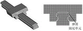
[0081] The bed-column bolt joint in the machine tool structure is as follows: figure 1 As shown, three M20 bolts are symmetrically distributed on both sides, and the bolt tightening torque is 500N·m. The contact surface pres...


PUM


Abstract

The invention discloses a method for dynamic modeling on an entire numerical control machine tool based on kinetic parameters of a joint part and analyzing and optimizing dynamic performance and an implementation scheme. The method disclosed by the invention takes a certain type of a vertical machining center as an example, dynamic model building and parameter identification are carried out on a bolt joint part, a guide rail sliding block joint part, a ball screw joint part and a bearing joint part, the dynamic performance of the entire numerical control machine tool is analyzed by combining finite element analysis software, an optimization object is established on the basis, a multi-objective optimization model is constructed, and the best optimization configuration is solved, so that the dynamic performance of the entire numerical control machine tool is optimized. Achievements of the method disclosed by the invention can be used for solving problems finite element analysis and optimization on the dynamic performance of the entire numerical control machine tool, and technical support is provided for improving processability of the numerical control machine tool.

Description

technical field [0001] The invention relates to the technical field of dynamic performance optimization design of a CNC machine tool, in particular to a finite element modeling and dynamic performance optimization method for a complete machine based on the dynamic characteristics of a joint of a CNC machine tool. Background technique [0002] With the continuous development of the advanced manufacturing industry, the modern machine tool manufacturing industry not only requires the machine tool to be light in weight, low in cost and easy to use, but also requires the machine tool to have higher and higher processing performance. Generally speaking, processing performance mainly includes two important aspects of machine tool processing quality and cutting efficiency. The processing quality of the machine tool is usually evaluated by the highest accuracy and surface finish that can be achieved by the machined parts, and the cutting efficiency of the machine tool is evaluated by...

Claims


Application Information

Patent Timeline
IPC IPC(8): G06F17/50
CPCG06F30/17G06F30/23G06F2111/04G06F2111/06
Inventor 殷国富殷勤邓聪颖王玲
Owner SICHUAN UNIV
Learn More