Eureka AIR delivers breakthrough ideas for toughest innovation challenges, trusted by R&D personnel around the world.

Attraction device and vacuum processing device

A technology for adsorption devices and main parts, applied in positioning devices, holding devices using electrostatic attraction, vacuum evaporation plating, etc., can solve the problems of reduced heat transfer capacity between the substrate and the adsorption device, and avoid the reduction of yield, Prevents transportation errors and prolongs life

Active Publication Date: 2017-05-31
ULVAC INC
View PDF8 Cites 2 Cited by
  • Summary
  • Abstract
  • Description
  • Claims
  • Application Information

AI Technical Summary

Problems solved by technology

[0008] However, in such a method, the heat transfer capability between the substrate and the adsorption device is reduced, and therefore, the original adsorption capacity cannot be fully exerted.

Method used


Image

  • Attraction device and vacuum processing device
  • Attraction device and vacuum processing device
  • Attraction device and vacuum processing device

Examples


Embodiment Construction

[0041] Hereinafter, embodiments of the present invention will be described with reference to the drawings.

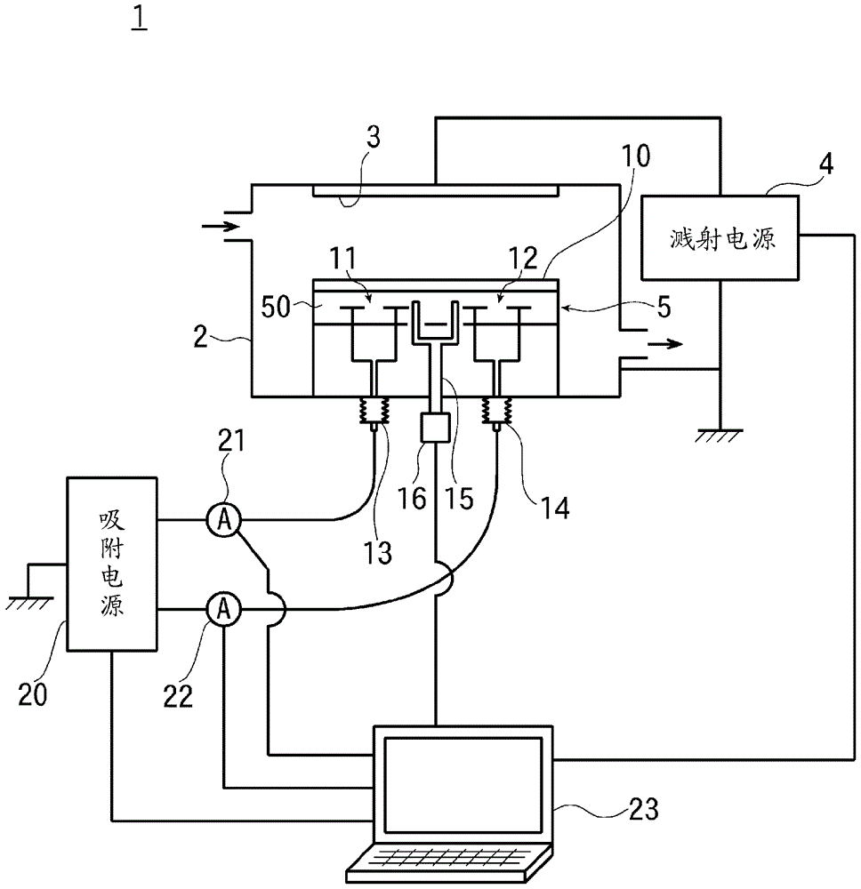
[0042] figure 1 It is a schematic configuration diagram of a sputtering apparatus which is an embodiment of the vacuum processing apparatus of the present invention.

[0043] exist figure 1 In the figure, reference numeral 2 denotes a vacuum chamber of the sputtering apparatus 1 of the present embodiment, and the vacuum chamber 2 is configured to be connected to an unshown vacuum exhaust system to introduce sputtering gas.

[0044]The target 3 as a film formation source is arrange|positioned in the upper part in the vacuum chamber 2. As shown in FIG.

[0045] The target 3 is connected to a sputtering power supply 4, and a negative bias voltage is applied thereto. In addition, the positive side of the sputtering power supply 4 is grounded together with the vacuum chamber 2 .

[0046] A suction device 5 for suction-holding a substrate (object to be suctioned) 10 is pr...


PUM


Abstract

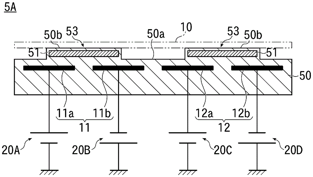
The invention provides a technique with which it is possible to suppress the generation of dust at the time of attracting and detaching an object to be attracted by reducing attraction force on a surface that comes into contact with the object to be attracted, and to control the attraction force of an attraction device so as to be uniform. This attraction device comprises: a main body part 50 including, in a dielectric, a pair of attraction electrodes 11, 12 of opposite polarities for attracting and holding a substrate 10; and electroconductive films 51 each arranged in a section on the attraction side of the main body part 50 with respect to the pair of attraction electrodes 11, 12, the electroconductive films being arranged so as to extend across an anode 11a and a cathode 11b of the paired attraction electrode 11 and an anode 12a and a cathode 12b of the paired attraction electrode 12, respectively.

Description

technical field [0001] The present invention relates to a suction device for suction-holding a substrate in a vacuum, and more particularly to a technology for a suction device for suction-holding a substrate having an insulating film on the back surface and an insulating substrate. Background technique [0002] Conventionally, in a sputtering apparatus or the like, an electrostatic adsorption apparatus has been widely used in order to precisely control the temperature of a substrate. As an apparatus for performing processes such as film formation on an insulating substrate such as glass in a vacuum, an adsorption device that adsorbs and holds an insulating substrate using a gradient force is widely used. In addition, when performing electrostatic adsorption on a substrate having an insulating film on the back surface, a method of increasing the adsorption voltage to increase the adsorption force is adopted. [0003] Conventionally, in this type of adsorption device, peelin...

Claims


Application Information

Patent Timeline
Patent Type & Authority Applications(China)
IPC IPC(8): H01L21/683H02N13/00
CPCC23C14/50C23C16/4586H01J37/3411H01L21/6833B23Q3/15H01L21/6838H02N13/00C23C14/34H01L21/6831
Inventor 前平謙不破耕早坂智洋
Owner ULVAC INC
Why Eureka
Eureka Blog
Learn More