
Switching power supply with multi-stage Darlington transistor

A technology of switching power supply and Darlington tube, which is applied in the direction of electrical components, adjusting electric variables, output power conversion devices, etc., can solve the problems of increasing the production cost of switching power supply, affecting the starting speed, controlling chip heating, etc., and achieving Save system cost, reduce power consumption, and reduce the effect of power supply capacitance

Inactive Publication Date: 2017-05-31
FREMONT MICRO DEVICES SHENZHEN LTD
View PDF7 Cites 3 Cited by
  • Summary
  • Abstract
  • Description
  • Claims
  • Application Information

AI Technical Summary

Problems solved by technology

[0003] The original switching tube is made of Metal Oxide Semiconductor (MOS for short), but due to the cost advantage of NPN transistors, more and more switching power supplies use NPN transistors instead of MOS transistors as switching tubes. However, when using NPN When the triode is used as a switch tube, the control chip needs to provide a large base current for the switch tube, which will easily cause a large power loss and cause serious heating problems in the control chip. Moreover, because the required base current is too large, it is necessary to Configure a large power supply capacitor to maintain the power supply voltage when the control chip is working, which will affect the startup speed and increase the preparation cost of the switching power supply

Method used


Image

  • Switching power supply with multi-stage Darlington transistor
  • Switching power supply with multi-stage Darlington transistor
  • Switching power supply with multi-stage Darlington transistor

Examples


Embodiment 1

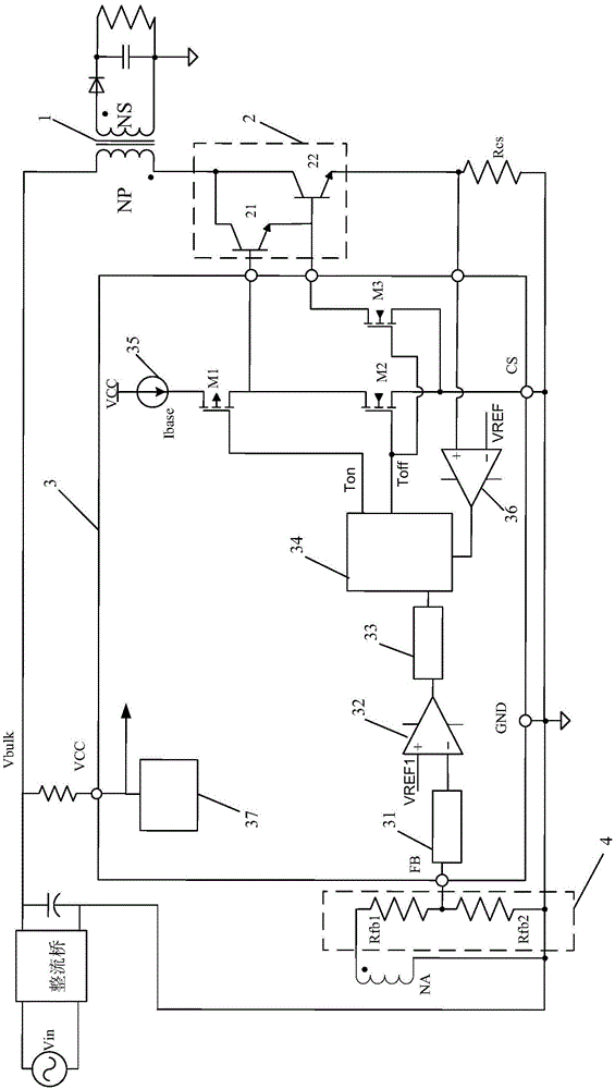
[0029] Embodiments of the present invention provide a switching power supply with multi-stage Darlington tubes, see figure 1 , the switching power supply may include: a transformer 1 , a switching tube 2 , a controller 3 , and a voltage dividing circuit 4 .

[0030] One end of the input winding NP of the transformer 1 is connected to the AC power supply Vin through a rectifier bridge, and the other end is connected to the switch tube 2. Both ends of the output winding NS of the transformer 1 are connected to the load (such as a light-emitting diode) through a rectifier diode. One end of the auxiliary winding NA is connected to the voltage dividing circuit 4 , and the other end thereof is grounded. The switch tube 2 may be a Darlington tube composed of at least two stages of NPN transistors.

[0031] The controller 3 may include: a sampling unit 31 , a first comparator 32 , a pulse frequency modulation unit 33 , a logic and driving unit 34 , a first MOS transistor M1 , a second...


PUM


Abstract

The invention discloses a switching power supply with a multi-stage Darlington transistor. The switching power supply comprises a transformer (1), a switching tube (2), a controller (2) and a bleeder circuit. The switching tube (2) is the Darlington transistor formed by at least two stages of NPN triodes, and the controller (3) comprises a sampling unit (31), a first comparator (32), a pulse frequency modulation unit (33), a logic and drive unit (34), a first MOS (metal oxide semiconductor) tube (M1), a second MOS tube (M2) and a current source (35). The switching power supply has advantages that by use of the multi-stage Darlington transistor as the switching tube, base drive current of the switching tube can be greatly lowered so as to reduce power consumption of the controller, chip temperature rise is reduced, and a driving power upper limit is substantially raised; in addition, power supply capacitance can be decreased correspondingly, so that system cost is saved.

Description

technical field [0001] The invention relates to the technical field of power supplies, in particular to a switching power supply with multi-stage Darlington tubes. Background technique [0002] Switching power supply is a kind of power supply that uses modern power electronic technology to control the time ratio of switching on and off to maintain a stable output voltage. [0003] The original switching tube is made of Metal Oxide Semiconductor (MOS for short), but due to the cost advantage of NPN transistors, more and more switching power supplies use NPN transistors instead of MOS transistors as switching tubes. However, when using NPN When the triode is used as a switching tube, the control chip needs to provide a large base current for the switching tube, which may easily cause a large power loss and cause serious heating problems in the control chip. Moreover, because the required base current is too large, it is necessary to Configure a large power supply capacitor to...

Claims


Application Information

Patent Timeline
Patent Type & Authority Applications(China)
IPC IPC(8): H02M3/335H02M7/219
CPCH02M3/33569H02M7/219
Inventor 许如柏黄裕泉
Owner FREMONT MICRO DEVICES SHENZHEN LTD
Learn More