
Punching sheet structure of permanent-magnet motor

A technology of permanent magnet motor and sheet punching, which is applied in the field of motor equipment, can solve problems such as the inability to meet the high-speed and high-torque output requirements of the motor, the weak magnetic field expansion capability of the motor, and the insufficient output of the motor, etc., to achieve low noise, strong and weak The effect of enhanced magnetic speed expansion ability and weak magnetic speed expansion ability

Pending Publication Date: 2017-05-31
WENLING JIUZHOU ELECTROMECHANICAL
View PDF1 Cites 13 Cited by
  • Summary
  • Abstract
  • Description
  • Claims
  • Application Information

AI Technical Summary

Problems solved by technology

[0004] The built-in rotor punching structure of the permanent magnet motor disclosed in the above-mentioned patent documents adopts a built-in radial V-shaped form, and the output of the motor is still not large enough, and the motor's weak magnetic field speed expansion capability is not strong enough to meet the high-speed and high-torque output of the motor. need

Method used


Image

  • Punching sheet structure of permanent-magnet motor
  • Punching sheet structure of permanent-magnet motor

Examples


Embodiment Construction

[0022] The following are specific embodiments of the present invention and in conjunction with the accompanying drawings, the technical solutions of the present invention are further described, but the present invention is not limited to these embodiments.

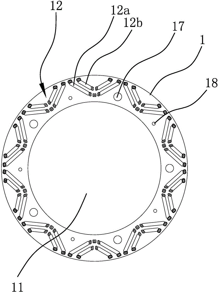
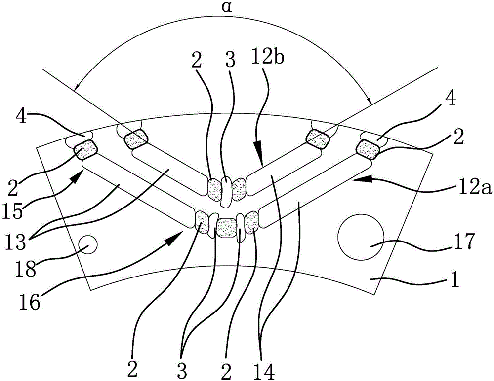
[0023] The technical solution in this embodiment is not limited by the number of rotor poles, and can be applied to rotor core structures of multi-pole motors such as four-pole, six-pole, eight-pole, and ten-pole. Such as figure 1 and figure 2 As shown, the present embodiment takes ten poles as an example. The punching structure of the permanent magnet motor includes a disc-shaped sheet 1, the middle part of the sheet 1 is provided with a shaft hole 11, and the sheet 1 is arranged along the circumferential direction of the shaft hole 11. Several groups of magnetic steel grooves 12 are distributed, each group of magnetic steel grooves 12 includes corresponding U-shaped grooves 12a and V-shaped grooves 12b, and the opening...


PUM


Abstract

The invention provides a punching sheet structure of a permanent-magnet motor, belongs to the technical field of motor manufacturing. By the punching sheet structure, the technical problems of small patented output and the like of an existing permanent-magnet motor are solved. The punching sheet structure comprises a round disc-shaped sheet body, wherein a plurality of V-shaped grooves are formed in the sheet body, a plurality of U-shaped grooves are further formed in the sheet body and are in one-to-one correspondence to the V-shaped groove, each pair of U-shaped groove and V-shaped groove forms a group of magnetic steel grooves, the magnetic steel grooves are distributed around the circumferential direction of the sheet body at intervals, openings of the U-shaped grooves and the V-shaped grooves face a peripheral surface of the sheet body, the U-shaped grooves are arranged between the V-shaped grooves and a shaft hole, and magnetic isolation bridges are arranged at lower ends of the U-shaped grooves and lower ends of the V-shaped grooves. In the punching sheet structure, each group of magnetic steel grooves comprise the U-shaped groove and the V-shaped groove which are arranged correspondingly, the U-shaped groove and the V-shaped groove are divided into two layers along a radial direction, thus, the magnetic resistance of a direct-axis magnetic path of the motor is increased, the magnetic conduction is reduced, the direct-axis inductance is reduced, the difference value between a quadrature-axis inductance and the direct-axis inductance is increased, the magnetic resistance torque of the motor is increased, and the output of the motor is increased.

Description

technical field [0001] The invention belongs to the technical field of motor equipment, and relates to a permanent magnet motor, in particular to a stamping structure of the permanent magnet motor. Background technique [0002] Permanent magnet motor is a kind of motor that uses permanent magnets to establish a magnetic field. It is widely used in automobiles, motorcycles, hand dryers, electric bicycles, battery vehicles, ships, aviation, machinery and other industries. It has high power factor, high efficiency, energy saving, etc. advantage. The magnetic isolation measure is an important factor affecting the no-load flux leakage coefficient of the permanent magnet motor. The magnetic isolation of the permanent magnet motor is generally realized by a magnetic isolation bridge. At present, the design of the built-in rotor punching structure in the permanent magnet motor is not very reasonable, which leads to the insufficient output of the motor after the motor is started, an...

Claims


Application Information

Patent Timeline
IPC IPC(8): H02K1/27
CPCH02K1/276
Inventor 杨云峰钟治平陈俊吉
Owner WENLING JIUZHOU ELECTROMECHANICAL
Learn More