
A portable vehicle charging system

An on-board charging and portable technology, applied in different battery charging, current collectors, electric vehicles, etc., can solve problems such as cumbersome and large limitations, and achieve the effect of reducing heat generation, intelligent overall function, and avoiding uncontrollable circuits.

Active Publication Date: 2019-11-19
深圳市电精灵销售有限公司
View PDF4 Cites 0 Cited by
  • Summary
  • Abstract
  • Description
  • Claims
  • Application Information

AI Technical Summary

Problems solved by technology

[0002] With the improvement of people's living standards, cars have entered thousands of households to continuously meet people's increasing needs, but at the same time it has also produced a series of negative effects, such as increasing energy prices, increasingly congested traffic conditions, and people's awareness of environmental protection. With continuous improvement, various new means of transportation have also been born, such as: electric folding cars, balance cars, twist cars, scooters and other small means of transportation have gradually entered people's lives; especially the increasing problem of parking and traffic congestion Seriously, it also prompts more and more people to choose this healthy, environmentally friendly, and fashionable way of travel. The beneficiaries include students, office workers, and even substitute drivers; but currently, the charging methods for such products can only be The AC-DC (AC to DC) conversion of the household mains power is completed by the charger, but this method has relatively large limitations, and it cannot be charged at all when it is away from the mains power supply, especially when it is outside, if it is out of power, it will not only be unusable but will not work. It has become a burden, which has a great impact on people who actually use it

Method used


Image

  • A portable vehicle charging system

Examples


Embodiment Construction

[0016] The present invention will be further described below in conjunction with accompanying drawing:

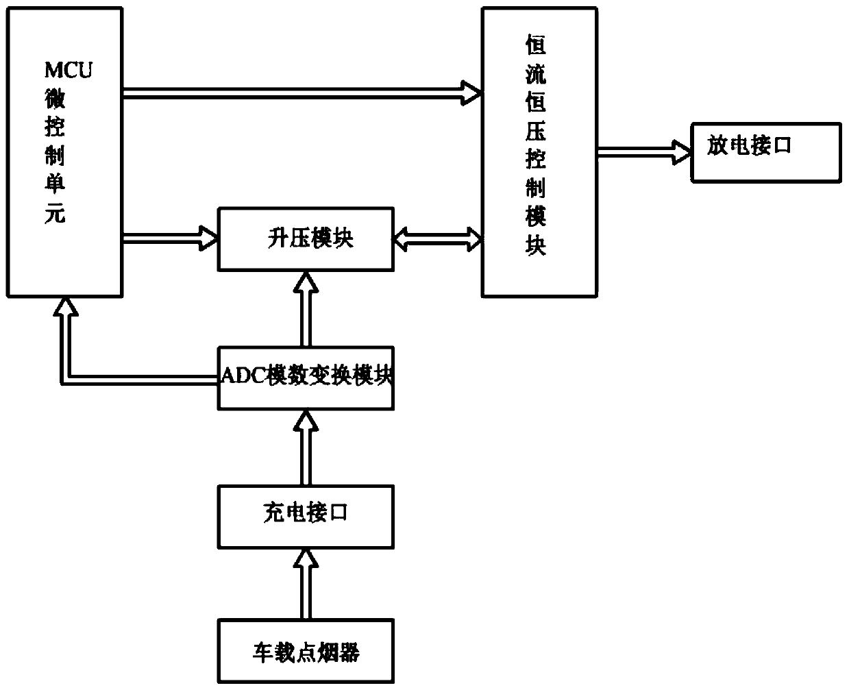
[0017] Such as figure 1 As shown in the system structure diagram of the present invention, the system of the present invention is mainly composed of a charging interface, an ADC analog-to-digital conversion module, a boost module, an MCU micro-control unit, a constant current and constant voltage control module, and a discharge interface; The charging interface is connected to the car cigarette lighter, and the car battery provides electric energy to the charging port through the car cigarette lighter; the car cigarette lighter is connected to the ADC analog-to-digital conversion module, and the first output terminal of the ADC analog-to-digital conversion module is connected to the MCU micro control unit. The input port is connected, and the second output end of the ADC analog-to-digital conversion module is connected with the second input end of the boost module; the firs...


PUM


Abstract

The invention discloses a portable car-mounted charging system. The system is mainly composed of a charging interface, an ADC analog to digital conversion module, a boosting module, an MCU microcontrol unit, a constant-current constant-voltage control module and a discharging interface. The charging interface is connected with a car-mounted cigarette lighter, and a car storage battery provides electric energy for the charging interface through the car-mounted cigarette lighter. The car-mounted cigarette lighter is connected with the ADC analog to digital conversion module, the first output end of the ADC analog to digital conversion module is connected with an input port of the MCU microcontrol unit, and the second output end of the ADC analog to digital conversion module is connected with the second input end of the boosting module. The first output end of the MCU microcontrol unit is connected with the first input end of the boosting module, and the second output end of the MCU microcontrol unit is connected with the first input end of the constant-current constant-voltage control module. The output end of the boosting module is connected with the second input end of the constant-current constant-voltage control module, and the output end of the constant-current constant-voltage control module is connected with the discharging interface. The system has the advantages of being exquisite in structure, convenient to use and the like.

Description

technical field [0001] The invention relates to the charging field, in particular to a portable vehicle charging system. Background technique [0002] With the improvement of people's living standards, cars have entered thousands of households to continuously meet people's increasing needs, but at the same time it has also produced a series of negative effects, such as increasing energy prices, increasingly congested traffic conditions, and people's awareness of environmental protection. With continuous improvement, various new means of transportation have also been born, such as: electric folding cars, balance cars, twist cars, scooters and other small means of transportation have gradually entered people's lives; especially the increasing problem of parking and traffic congestion Seriously, it also prompts more and more people to choose this healthy, environmentally friendly, and fashionable way of travel. The beneficiaries include students, office workers, and even substi...

Claims


Application Information

Patent Timeline
Patent Type & Authority Patents(China)
IPC IPC(8): H02J7/00
CPCH02J7/00H02J7/00304H02J7/0031H02J7/0036H02J7/0047
Inventor 刘厚德冼焕明何凌云
Owner 深圳市电精灵销售有限公司
Learn More