
Coupled optoelectronic oscillator

A photoelectric oscillator and photoelectric oscillation technology, which is applied in the field of mobile communication, can solve the problems of complex loop structure, limited repetition frequency, and poor stability in COEO, and achieve the goal of reducing volume, solving the limitation of working frequency, and realizing synchronous output Effect

Pending Publication Date: 2017-05-31
CHINA ACADEMY OF ELECTRONICS & INFORMATION TECH OF CETC
View PDF6 Cites 4 Cited by
  • Summary
  • Abstract
  • Description
  • Claims
  • Application Information

AI Technical Summary

Problems solved by technology

[0007] In order to overcome the shortcomings of the current COEO, such as complex loop structure, large volume, poor stability, and limited repetition frequency, the present invention provides a mutual coupling photoelectric oscillator

Method used


Image

  • Coupled optoelectronic oscillator
  • Coupled optoelectronic oscillator
  • Coupled optoelectronic oscillator

Examples


Embodiment Construction

[0017] Exemplary embodiments of the present disclosure will be described in more detail below with reference to the accompanying drawings. Although exemplary embodiments of the present disclosure are shown in the drawings, it should be understood that the present disclosure may be embodied in various forms and should not be limited by the embodiments set forth herein. Rather, these embodiments are provided for more thorough understanding of the present disclosure and to fully convey the scope of the present disclosure to those skilled in the art.

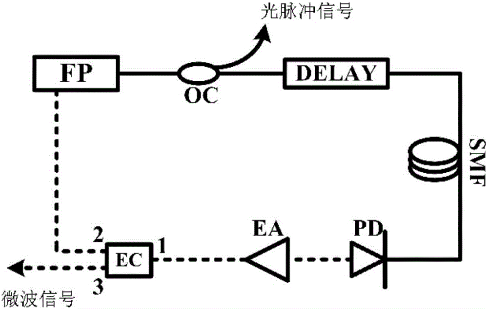
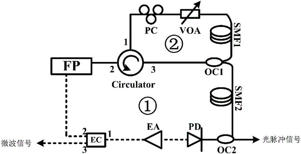
[0018] In order to overcome the disadvantages of complex loop structure, large volume, poor stability, and limited repetition frequency in the current COEO, the present invention provides a mutual coupling optoelectronic oscillator. The present invention will be further described in detail below with reference to the accompanying drawings and embodiments. It should be understood that the specific embodiments described here are only ...


PUM


Abstract

The invention discloses a coupled optoelectronic oscillator. The coupled optoelectronic oscillator comprises an FP (Fabry-Perot) laser and an optoelectronic oscillation loop, wherein the FP laser is used for producing multi-longitudinal-mode lasing and sends the multi-longitudinal-mode lasing to the optoelectronic oscillation loop; the FP laser receives injecting signals produced by the optoelectronic oscillation loop, finishes mode locking under the driving of the injecting signals and produces the multi-longitudinal-mode lasing after mode locking; the optoelectronic oscillation loop is used for receiving the multi-longitudinal-mode lasing sent by the FP laser, producing injecting signals and injecting the signals back to the FP laser; further, the optoelectronic oscillation loop receives the mode-locked multi-longitudinal-mode lasing sent by the FP laser and outputs optical pulse signals and microwave signals according to the multi-longitudinal-mode lasing after mode locking. By the aid of the technical scheme, the system size is greatly reduced, the cost is reduced, high-frequency and low-threshold microwave oscillation can be obtained under the condition that a microwave narrow-band filter is not used, and the limitation of the microwave filter to working frequency is eliminated.

Description

technical field [0001] The invention relates to the field of mobile communication, in particular to a mutual coupling photoelectric oscillator. Background technique [0002] As a microwave signal generator with high frequency and low phase noise, the Optoelectronic Oscillator (OEO) plays an important role in the fields of optical fiber communication, wireless communication, radar system, sensing system, high-precision measurement and precision instruments. Value. OEO is a photoelectric hybrid positive feedback oscillating loop, which uses a high-Q, low-loss time-delay fiber as a time delay and energy storage unit, thereby generating high-purity, low-phase-noise microwave signals. A notable feature of OEO is that the phase noise of its output microwave signal has nothing to do with the operating frequency, which is a huge advantage over electronic microwave oscillators. [0003] On the basis of traditional OEO, a coupled optoelectronic oscillator (Coupled Optoelectronic Osc...

Claims


Application Information

Patent Timeline
IPC IPC(8): H01S1/02
CPCH01S1/02
Inventor 蔺博潘碧玮
Owner CHINA ACADEMY OF ELECTRONICS & INFORMATION TECH OF CETC
Learn More