
Power battery thermal management method and system

A thermal management system, power battery technology, applied in the direction of secondary batteries, circuits, electrical components, etc., can solve the problem of lack of battery temperature rising trend, and achieve the effect of improving safety

Pending Publication Date: 2017-05-31
HUIZHOU BNET TECH CO LTD
View PDF14 Cites 22 Cited by
  • Summary
  • Abstract
  • Description
  • Claims
  • Application Information

AI Technical Summary

Problems solved by technology

Although this process can control the temperature of the battery, it lacks the judgment of the rising trend of the battery temperature

Method used


Image

  • Power battery thermal management method and system
  • Power battery thermal management method and system
  • Power battery thermal management method and system

Examples


Embodiment 1

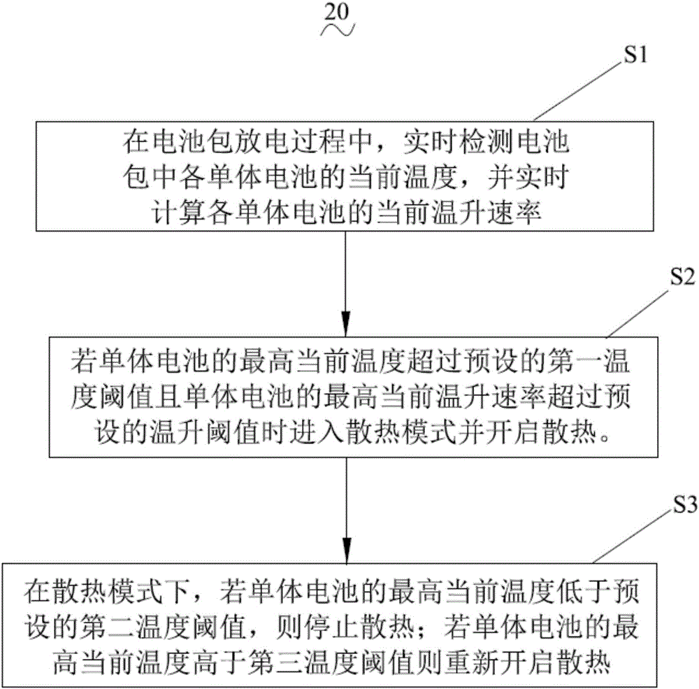
[0054] see figure 1 , a power battery thermal management method 20, applied to a charging process or a discharging process of a battery pack, comprising the following steps:

[0055] Step S1, during the discharge process of the battery pack, detect the current temperature of each single battery in the battery pack in real time, and calculate the current temperature rise rate of each single battery in real time.

[0056] Step S2, if the highest current temperature of the single battery exceeds the preset first temperature threshold and the highest current temperature rise rate of the single battery exceeds the preset temperature rise threshold, enter the heat dissipation mode and turn on heat dissipation. Specifically, the first temperature threshold is preferably 28°C to 32°C. In this embodiment, 30° C. is used as an example; the temperature rise threshold is preferably 1° C. / min˜3° C. / min. In this embodiment, 2°C / min is selected as an example.

[0057] Step S3, in the heat...

Embodiment 2

[0073] see figure 2 , the present invention also provides a power battery thermal management system 10, which includes: a temperature detection unit 110, which detects the current temperature of each single battery in the battery pack in real time. The temperature processing unit 120 judges the validity of the current temperature of each single battery, and eliminates invalid temperature values. The temperature rise rate calculation unit 130 calculates the current temperature rise rate of each single battery according to the current temperature of each single battery after removing invalid temperature values. The heat dissipation control unit 210 controls the working state of the heat dissipation module according to the current temperature of each single battery and the current temperature rise rate of each single battery after removing invalid temperature values. The heat dissipation module 220 performs corresponding operations according to the control instructions of the h...


PUM


Abstract

The invention discloses a power battery thermal management method and system applied to a charging process or discharging process of a battery pack. The method comprises the following steps: in the discharging process of the battery pack, detecting the current temperature of each single battery in the battery pack in real time, and calculating the current temperature rise rate of each single battery in real time; if the highest current temperature of each single battery exceeds a first preset temperature threshold value and the highest current temperature rise rate of each single battery exceeds a preset temperature rise threshold value, entering a radiation mode and starting radiation; in the radiation mode, if the highest current temperature of each single battery is lower than a second preset temperature threshold value, stopping radiation; if the highest current temperature of each single battery is higher than a third temperature threshold value, restarting radiation. According to the method and the system, a radiation module can also be controlled to be started or stopped to keep the battery pack within a relatively stable temperature range according to the temperature rise rate of each single battery in a discharging mode of the battery pack, so that the safety of the battery pack is improved.

Description

technical field [0001] The invention relates to the field of power battery thermal management, in particular to a power battery thermal management method and system. Background technique [0002] Under the advocacy of green energy, power batteries, as the main source of power for new energy electric vehicles, play an irreplaceable role in the vehicle system, and are increasingly popular with the public. At the same time, how to maximize the more effective use of battery packs has become the focus of attention. [0003] The batteries in the battery pack need to be heated to a certain extent. For example, when the battery is being charged, it is necessary to detect the temperature of each battery. If the temperature of the battery is too low, the battery will not be fully charged, because the capacity of the battery has a certain relationship with the temperature. The battery is calculated based on the standard temperature of 25 degrees. When the temperature drops by 1 degr...

Claims


Application Information

Patent Timeline
IPC IPC(8): H01M10/617H01M10/625H01M10/633
CPCH01M10/617H01M10/625H01M10/633H01M2010/4271Y02E60/10
Inventor 黄隆庚
Owner HUIZHOU BNET TECH CO LTD
Learn More