
Heat sink and design method thereof and device and transformer

A design method and heat sink technology, applied in the field of transformers, can solve the problem that transformer heat sinks cannot meet the requirements of heat sink volume and heat dissipation efficiency, etc.

Active Publication Date: 2017-05-31
GLOBAL ENERGY INTERCONNECTION RES INST CO LTD +2
View PDF7 Cites 3 Cited by
  • Summary
  • Abstract
  • Description
  • Claims
  • Application Information

AI Technical Summary

Problems solved by technology

[0008] Therefore, the technical problem to be solved by the present invention is that the transformer cooling fins in the prior art cannot meet the requirements of the new transformer for the volume and heat dissipation efficiency of the cooling fins

Method used


Image

  • Heat sink and design method thereof and device and transformer
  • Heat sink and design method thereof and device and transformer
  • Heat sink and design method thereof and device and transformer

Examples


Embodiment 1

[0038] In this embodiment, a method for designing a heat sink of a transformer is provided, which is used to design the optimal size of a heat sink in a transformer, wherein the optimal size refers to the external size, heat dissipation, maximum temperature rise and fan drive of the entire heat sink Under the condition of given power, the radiator structure is optimized to minimize its volume or mass.

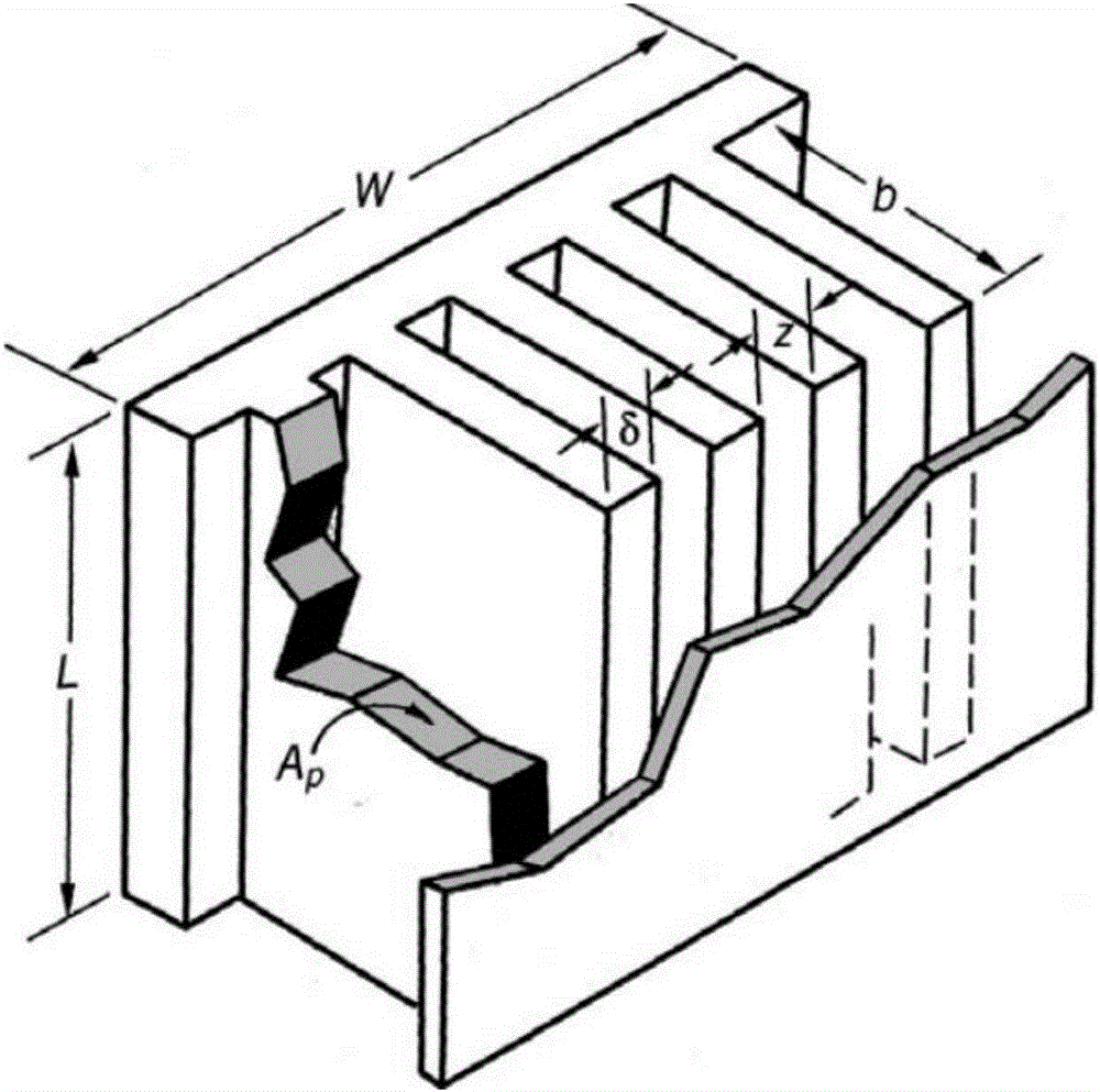
[0039] The structure of the heat sink is as figure 1 As shown, the meanings of the dimensions represented by each letter are as follows: L and W are the dimensions of the heat sink base, δ indicates the thickness of the fins, z indicates the spacing of the fins, b indicates the height of the fins, A p Indicates the cross-sectional area of ​​the fin in the direction of heat conduction. The purpose of the design method of the heat sink is to give the dimensions L and W of the base of the fin, and the air inlet temperature T m,i , susceptor temperature T s , then the base exces...

Embodiment 2

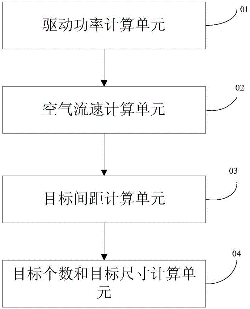
[0097] In this embodiment, a design device for heat sink is provided, such as image 3 shown, including:

[0098] The driving power calculation unit 01 is used to obtain the driving power of the cooling fan;

[0099] The air velocity calculation unit 02 is used to calculate the air velocity under different cooling fin pitches according to the driving power;

[0100] A target spacing calculation unit 03, configured to calculate the target spacing of the cooling fins according to the different spacings of the cooling fins and the corresponding air velocity;

[0101] The target number and target size calculation unit 04 is used to calculate the target number of cooling fins according to the height, and distribute the total heat to each cooling fin to calculate the target size of the cooling fins.

[0102] Wherein, the driving power calculation unit includes:

[0103] P N = u m zΔp

[0104] Among them, Δp represents the pressure drop of the air, z represents the distance betwe...


PUM


Abstract

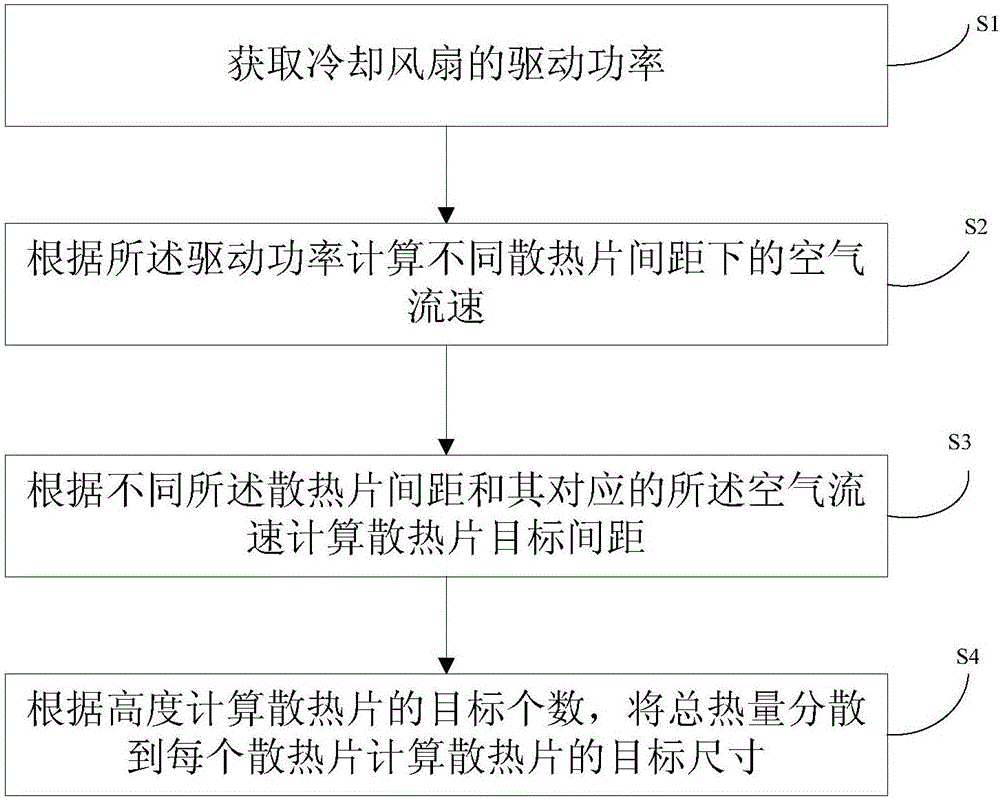
The invention provides a transformer heat sink design method. The method comprises the steps that the driving power of a cooling fan is obtained; according to the driving power, air velocity under different heat sink spacing is calculated; according to the different heat sink spacing and the air velocity corresponding to the different heat sink spacing, heat sink target spacing is calculated; according to the height, target number of heat sinks is calculated and the total heat is distributed to each heat sink to calculate the target sizes of the heat sinks. In the heat sink design method, heat dissipating capacity of the heat sinks is increased to the maximum extent, and at the same time, the weight and the volume of the heat sinks are reduced. Under a specific heat dissipation demand, the heat sink design method is capable of effectively improving the utilization ratio of heat sink materials, reducing the volume of the heat sinks, effectively reducing stable temperature rise of a high-frequency transformer and enlarging the largest capacity of the high-frequency transformer.

Description

technical field [0001] The invention relates to the field of transformers, in particular to a heat sink, a design method and device thereof, and a transformer. Background technique [0002] Based on power electronics technology, scholars at home and abroad have begun to explore and research a new type of intelligent transformer that realizes power conversion - Power Electronic Transformer (PET for short), also known as Solid-State Transformer (SST for short). As a highly controllable new type of substation equipment, the power electronic transformer is characterized by the ability to flexibly control the voltage amplitude and phase of the primary and secondary sides of the transformer to meet many new requirements for the future development of smart grids. In the realization of the high-power topology of the power electronic transformer, the high-frequency transformer body in the middle is the most basic and most important electromagnetic component. As the design capacity c...

Claims


Application Information

Patent Timeline
IPC IPC(8): H01F27/22H01F41/00
CPCH01F27/22H01F41/00
Inventor 才志远刘海军李琳尹毅然
Owner GLOBAL ENERGY INTERCONNECTION RES INST CO LTD
Learn More