Compound pressure and vacuum gage for displaying different measuring ranges by linear scales

A technology of pressure vacuum gauge and linear scale, applied in the direction of measuring fluid pressure, vacuum gauge, measuring device, etc., can solve the problem of inaccurate measurement, and achieve the effect of simple device and accurate measurement

Active Publication Date: 2017-05-31
慈溪欧卡特仪表科技有限公司
View PDF6 Cites 3 Cited by
  • Summary
  • Abstract
  • Description
  • Claims
  • Application Information

AI Technical Summary

Problems solved by technology

[0002] At present, the pressure vacuum gauges on the market are all linear, and the vacuum degree or pressure is represented by the deformation of a deformed plate, which is reflected in the scale of the pressure vacuum gauge, which is symmetrical and uniform. However, in actual use Among them, when the negative pressure is 1 bar, it is close to vacuum, and the positive pressure to be measured by the pressure gauge is usually much greater than this, so the linear symmetrical pressure vacuum gauge is not very accurate when measuring negative pressure

Method used


Image

  • Compound pressure and vacuum gage for displaying different measuring ranges by linear scales
  • Compound pressure and vacuum gage for displaying different measuring ranges by linear scales
  • Compound pressure and vacuum gage for displaying different measuring ranges by linear scales

Examples


Embodiment Construction

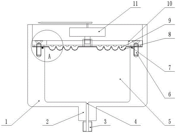
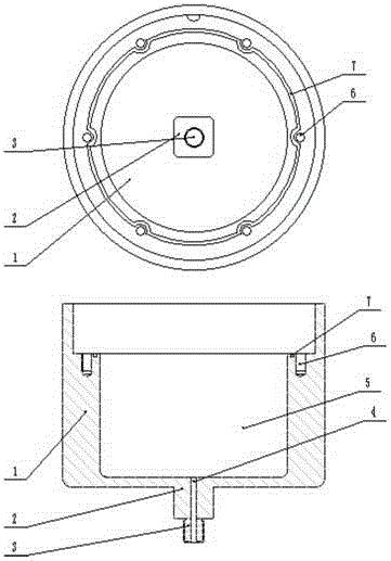
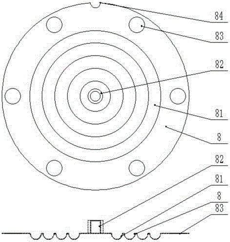
[0029] Such as Figure 1-7 As shown, a pressure vacuum gauge with a linear scale displaying different ranges in the embodiment of the present invention includes: the pressure gauge plate 1 is a hollow cylinder, the bottom of the pressure gauge plate 1 is connected to the joint 3 through the flange 2, and the inside of the joint 3 is processed air Channel 4, there is a sinking shoulder on the inner side of the pressure dial 1, and the bolt hole 6 and the sealing groove 7 are processed at the sinking shoulder. The sealing groove 7 is a special-shaped structure, and there is a semicircular inner transition at the position of the bolt hole 6. The sealing ring and the sinking shoulder are also processed with a positioning protrusion; the vacuum deformation plate 8 is in the shape of a circular sheet, and a sleeve 82 is fixedly installed in the middle position, and a pointer mechanism 11 is connected above the sleeve 82, and the pointer mechanism 11 can move the vacuum deformation pl...


PUM


Abstract

The invention discloses a compound pressure and vacuum gage for displaying different measuring ranges by linear scales. The lower part of a pressure gage shell is connected with a joint through a flange; an air passage is processed in the pressure gage shell; a vacuum deformation plate and a pressure deformation plate are stacked and then are fixedly arranged inside the pressure gage shell through a bolt; a closed air chamber is formed between the vacuum deformation plate and the pressure gage shell; the middle of the vacuum deformation plate is fixedly provided with a sleeve pipe used for mounting a pointer mechanism. When the compound pressure and vacuum gage works, when a vacuum exists in the air passage, the vacuum deformation plate makes the sleeve pipe to downwards move through the deformation of a vacuum deformation ring, and a pointer is dragged to anticlockwise deflect; when pressure exists in the air passage, the vacuum deformation plate compresses the pressure deformation plate for deformation, the sleeve pipe is enabled to upwards move, and the pointer is dragged to clockwise deflect; through a thickness difference between the vacuum deformation plate and the pressure deformation plate, deflection scales are enabled to be different. According to a pressure gage, the pointer is enabled to carry out inverse deflection through using the vacuum deformation plate and the pressure deformation plate; meanwhile, by utilizing the thickness difference between the vacuum deformation plate and the pressure deformation plate, the deflection scales are enabled to be different. A device is simple and reliable.

Description

technical field [0001] The invention relates to instruments and meters, in particular to a pressure vacuum gauge with a linear scale displaying different measuring ranges. Background technique [0002] At present, the pressure vacuum gauges on the market are all linear, and the vacuum degree or pressure is represented by the deformation of a deformed plate, which is reflected in the scale of the pressure vacuum gauge, which is symmetrical and uniform. However, in actual use Among them, when the negative pressure is 1 bar, it is close to vacuum, and the positive pressure to be measured by the pressure gauge is usually much greater than this. Therefore, the linear symmetrical pressure vacuum gauge is not very accurate when measuring negative pressure. [0003] A non-linear symmetrical pressure vacuum gauge mentioned in the present invention measures positive pressure and negative pressure respectively through the action of two pressure plates. When measuring negative pressure,...

Claims


Application Information

Patent Timeline
IPC IPC(8): G01L21/00G01L19/10G01L19/16
CPCG01L19/10G01L19/16G01L21/00
Inventor 陆志江
Owner 慈溪欧卡特仪表科技有限公司
Why Eureka
Try Eureka