Friction force and friction coefficient experiment and measurement device and measurement method
What is Al technical title?
Al technical title is built by PatSnap Al team. It summarizes the technical point description of the patent document.
A technology of friction coefficient and measuring device, which is applied in the direction of measuring device, measuring force, and mechanical device, etc. It can solve the problems of unbalanced human force, insufficient precision of dynamometer, and inconvenient reading, so as to avoid human error and have a wide range of applications , to avoid the effect of secondary error
Inactive Publication Date: 2019-09-06
LINYI UNIVERSITY
View PDF7 Cites 0 Cited by
Summary
Abstract
Description
Claims
Application Information
AI Technical Summary
This helps you quickly interpret patents by identifying the three key elements:
Problems solved by technology
Method used
Benefits of technology
Problems solved by technology
However, there are also deficiencies in horizontal measurement. The most prominent is the provision of traction. The most primitive is manual traction, that is, the movement of the measured object is pulled by hand, but the force provided by the hand is not balanced, and it is difficult to make the object move along the horizontal direction. uniform motion
Later, people also improved the friction measurement device, using heavy objects or electric motors to pull, the traction provided by these two methods is constant, but since we are measuring the magnitude of friction, we cannot predict the traction provided. How much traction should be, which causes traction is not equal to friction, so the final measurement result is also wrong
In addition, in this method, the dynamometer moves with the measured object during measurement, which causes inconvenience in reading, and the accuracy of most dynamometers is not enough, and the error is large
Method used
Image
Click on the blue label to locate the original text in one second.
Reading with bidirectional positioning of images and text.
Examples
Embodiment Construction
[0049] Combine below Figure 1-Figure 7 Specific embodiments of the present invention are described in detail:
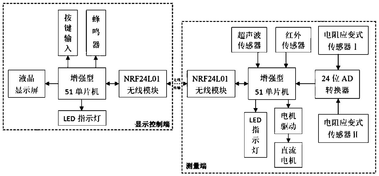
[0050]The invention includes a measurement terminal and a display control terminal, the display control terminal and the measurement terminal are separated from each other, and they perform data communication through wireless.
[0051] It should be noted that although image 3 Only the principle block diagram of the present invention is given in the present invention, but, specific components and parts and the corresponding connection relationship between them are given, according to image 3 Combining with the common knowledge of those skilled in the art, it is easy to implement the detailed circuit connection of the present invention, so details are not repeated here.
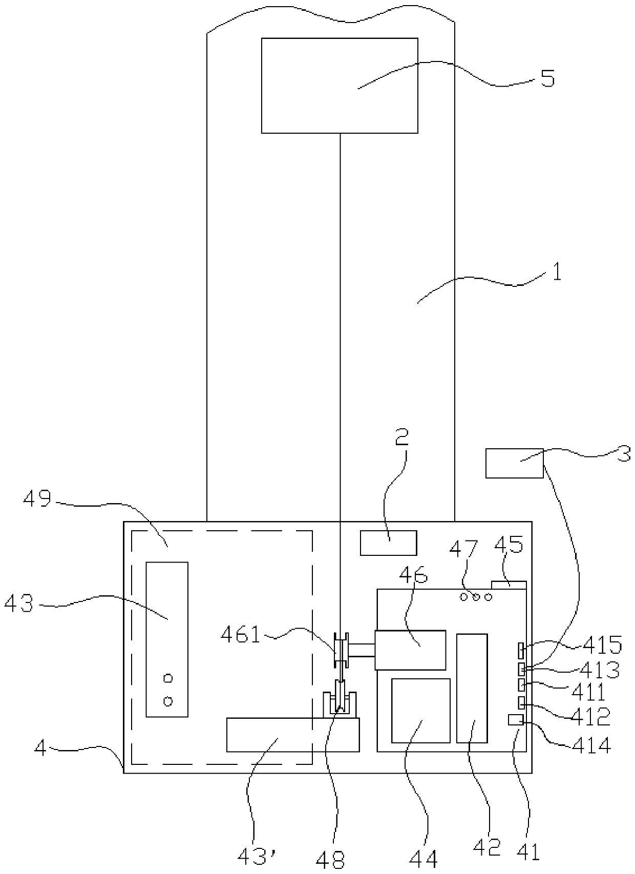
[0052] Such as figure 1 and image 3 As shown, the measuring end includes a friction bearing plate 1, an ultrasonic velocity sensor 2, a motor stop switch 3, a base 4, and a circuit board 41 ar...
PUM
Abstract
The invention relates to a friction force and friction coefficient experiment and measurement device and method. A measurement end of the measurement device comprises a friction bearing board, a supersonic wave speed measurement sensor, a motor stop switch, a foundation, a circuit board, a single-chip microcomputer, a resistor strain type sensor, an AD converter, a wireless transceiver module, a DC motor, an LED indication lamp, a pulley and a weighing disc, wherein the resistor strain type sensor I is provided with the weight disc, one end of the resistor strain type sensor is provided with the pulley, an output shaft of the DC motor has a coiling wheel, non-elastic wire is wound through the coiling wheel and is then connected with a detected object, a PID algorithm is utilized by the single-chip microcomputer to adjust PWM driven by the motor to pull the detected object to do uniform motion, and a display control end of the measurement device comprises a single-chip microcomputer, a lithium cell, a liquid crystal display screen, a wireless transceiver module, a button, a buzzer and an LED indication lamp. The measurement device is advantaged in that quick, simple, visual and accurate measurement can be realized, not only can the measurement device be applied to physics experiment teaching, but also the measurement device can be applied to professional friction force and smoothness detection.
Description
technical field [0001] The invention relates to a friction force and friction coefficient measurement device, in particular to a friction force and friction coefficient experiment and measurement device and a measurement method. Background technique [0002] The measurement of friction force has always been a difficult point in the design of physical experiments. The traditional methods for measuring friction force in physical experiments include the inclined plane method and the horizontal method. The slope method is to place the measured object on a platform, and then gradually increase the tilt angle of the platform. When the measured object starts to slide due to gravity, measure the tilt angle, and calculate the friction force and friction coefficient according to the decomposition of the force. . The horizontal method is to place the measured object horizontally on a horizontal platform, apply traction to make the measured object move at a uniform speed, and the tract...
Claims
Application Information
Patent Timeline
Application Date:The date an application was filed.
Publication Date:The date a patent or application was officially published.
First Publication Date:The earliest publication date of a patent with the same application number.
Issue Date:Publication date of the patent grant document.
PCT Entry Date:The Entry date of PCT National Phase.
Estimated Expiry Date:The statutory expiry date of a patent right according to the Patent Law, and it is the longest term of protection that the patent right can achieve without the termination of the patent right due to other reasons(Term extension factor has been taken into account ).
Invalid Date:Actual expiry date is based on effective date or publication date of legal transaction data of invalid patent.