an umbrella dryer

A technology for dryers and umbrellas, which is applied in the direction of dryers, drying, partial agitation dryers, etc., which can solve the problems of high requirements for working environment conditions, single drying control, and reduced drying efficiency, so as to achieve faster dripping fall, ensure drying efficiency, and improve drying efficiency

Inactive Publication Date: 2019-06-21
南京蒙托克环保科技有限公司
View PDF3 Cites 1 Cited by
  • Summary
  • Abstract
  • Description
  • Claims
  • Application Information

AI Technical Summary

Problems solved by technology

Most of the existing umbrella dryers have a square structure with umbrella insertion slots or holes. The existence of the slots or holes makes an extra layer of interlayer between the umbrella and the hot air, reducing the drying efficiency; The handle of the umbrella is exposed, and the space where the umbrella is located is open, resulting in waste of energy and reducing the drying efficiency; single drying control, waste of energy, and easy to damage the umbrella; the requirements for the working environment are relatively high; in addition, the heating device of the umbrella dryer Located inside the drying chamber, it is very easy to cause damage to the heating device caused by moisture in the chamber

Method used


Image

  • an umbrella dryer
  • an umbrella dryer
  • an umbrella dryer

Examples


Embodiment 1

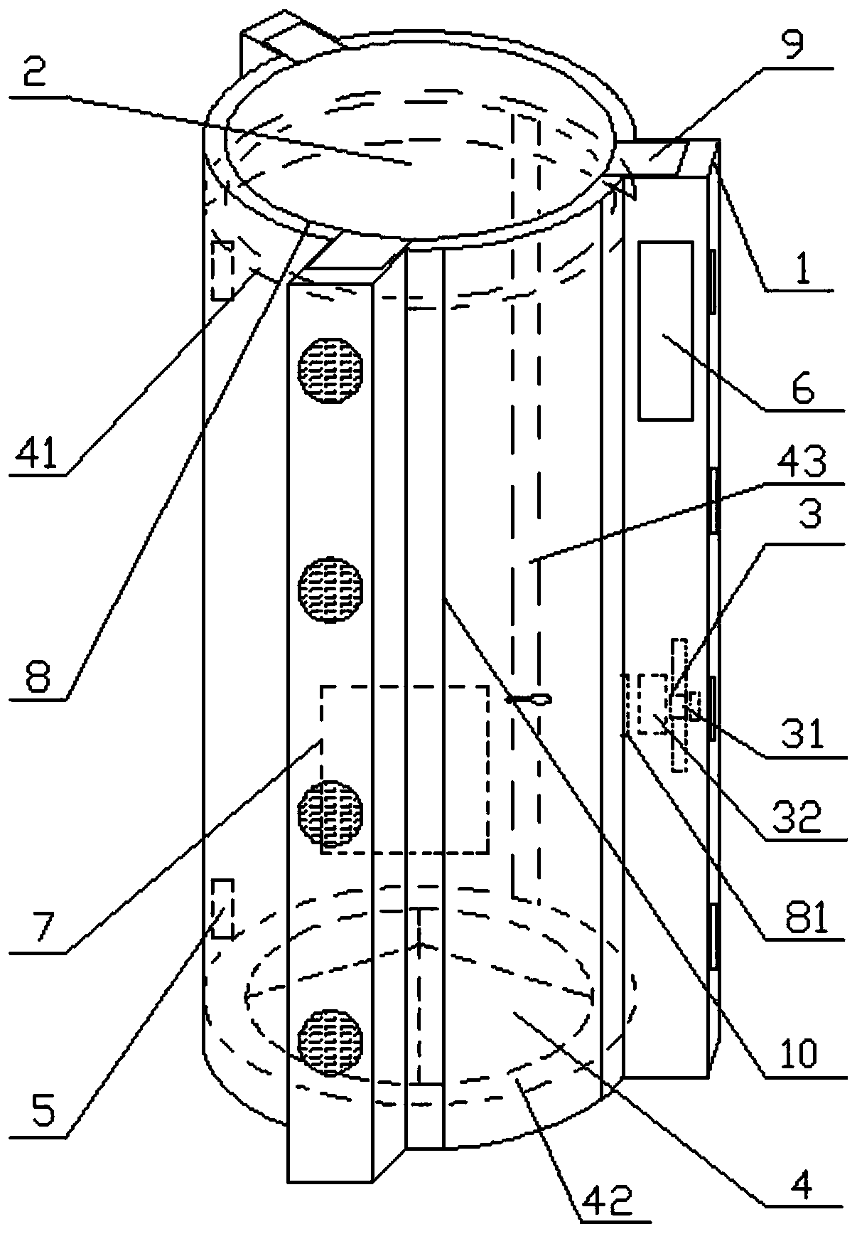
[0030] Such as figure 1 The umbrella dryer shown includes a housing 1, a drying chamber 2, a heating device 3, a water collecting device 4, a temperature control sensor 5 and a control panel 6, wherein,

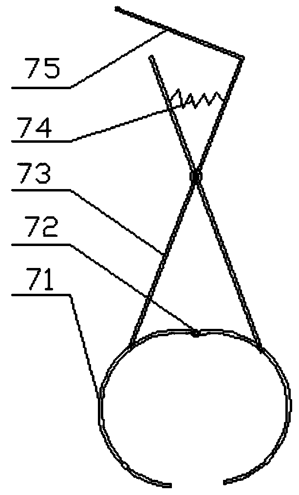
[0031] The middle and lower part of the drying chamber 2 is provided with a clamping device 7 for vertically fixing the umbrella, which is beneficial for the device to be applicable to various umbrellas with different heights. Such as figure 2 , the clamping device 7 includes a clamping claw and a clamping arm, the clamping claw includes two arc clamps 71 whose one ends are all fixed on the same turning point 72, and the clamping arm includes two cross-fixed Connecting rod 73, one end of two connecting rods 73 is respectively fixed on two arc clamps 71, and two connecting rods 73 are intersected away from the included angle of clamping claw and be provided with pre-tightening spring 74 between, two connecting rods 73 One end near the pretension spring 74 extends through th...

Embodiment 2

[0041] The difference between this embodiment and embodiment 1 is that

[0042] The clamping device 7 includes a clamping claw, and the control panel 6 is provided with a clamping switch, which controls the loosening and clamping of the clamping claw through a relay and a motor;

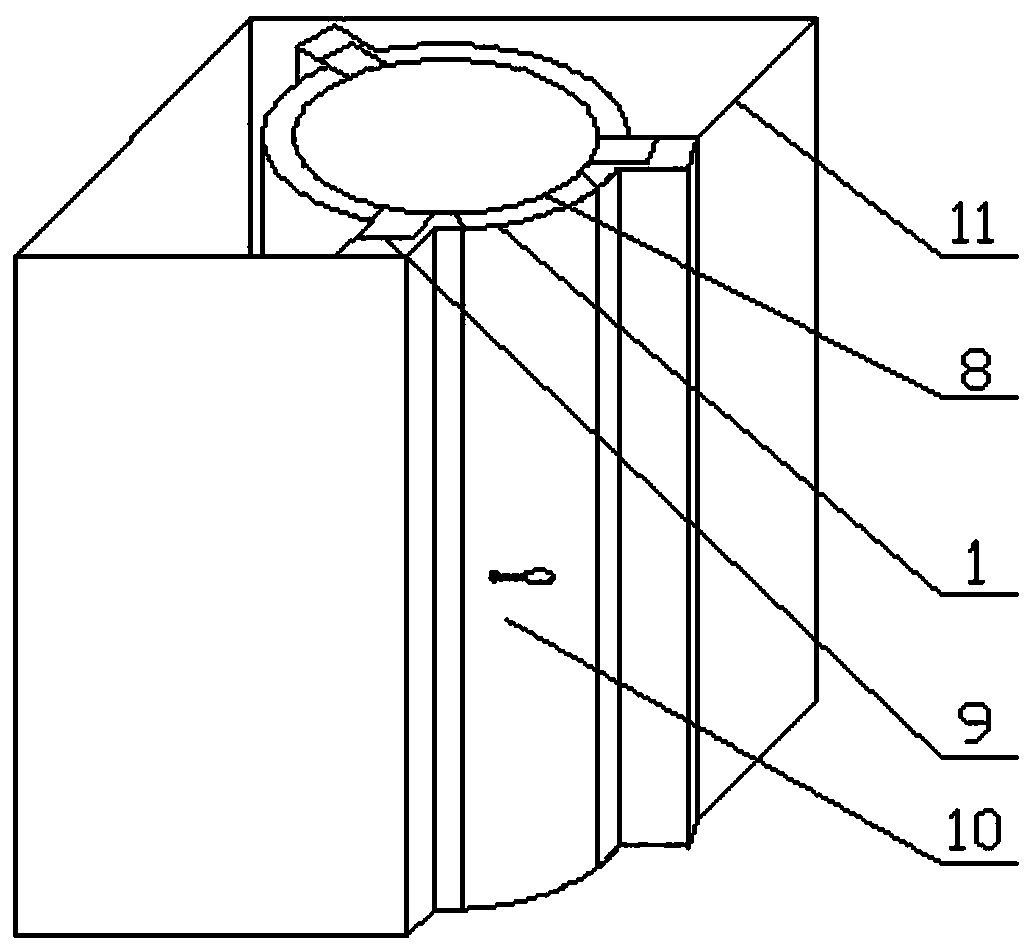
[0043] Such as image 3 , the housing 1 and the old object recovery box 11 are integrally structured.

[0044] Others are the same as embodiment 1.

[0045] The drying principle of this umbrella drying machine is the same as embodiment 1.

[0046] During actual use, first open the single door 10, press the and clamping switch on the control panel 6 to open the clamping claws, put the umbrella vertically into the clamping device 7, and then press the clamping switch to clamp Clamp the umbrella with claws, close the single door 10, turn on the power switch on the control panel 6, select the upper and lower heating devices 3 through the fan combination knob, then the middle heating device 3 will not ...


PUM


Abstract

The invention discloses an umbrella dryer, and belongs to the field of drying equipment. The umbrella dryer comprises a shell, a drying cavity, a heating device, a water collecting device, temperature control sensors and a control panel, a clamping device for vertically fixing umbrellas is arranged in the drying cavity, a double-layer barrel wall is arranged outside the drying cavity, an inner layer of the barrel wall is made of heat insulation materials, the drying cavity is closed, a single door is arranged on the barrel wall, the heating device is arranged in a heating box and fixed onto an outer layer of the barrel wall through the heating box, a cold air inlet is formed in the shell and corresponds to the heating device, a hot air inlet is formed in the barrel wall, hot air enters the drying cavity through the hot air inlet, the water collecting device comprises an upper water collecting channel, a lower water collecting channel and a gutter, the upper water collecting channel and the lower water collecting channel are arranged at the top and the bottom of the drying cavity respectively and communicated through the gutter, the upper portion and the lower portion of the inner side wall of the barrel wall are respectively provided with one temperature control sensor, and a temperature display is arranged on the control panel positioned on the outer surface of the shell and electrically connected with the temperature control sensors. The umbrella dryer has the advantages of high heating efficiency, simple structure, low cost and the like.

Description

technical field [0001] The invention relates to the field of drying equipment, in particular to an umbrella dryer. Background technique [0002] The development of social economy determines that people pay more and more attention to the cleanliness and comfort of the surrounding working environment and living environment, especially some public places such as shopping malls and office buildings with high population density and high traffic. When traveling in rainy days, umbrellas have become a must-have tool for people, but the accumulation of water in umbrellas leads to slippery ground, which is prone to collisions, falls and other phenomena that affect personal safety, and it is also easy to cause contamination of valuables in shopping malls and office buildings. [0003] In order to solve the above problems, most of the methods adopted are as follows: 1. Set up a temporary storage place for umbrellas. The space is limited, the storage capacity is too small, and it is easy...

Claims


Application Information

Patent Timeline
Patent Type & Authority Patents(China)
IPC IPC(8): F26B9/04F26B21/00F26B25/08
CPCF26B9/04F26B21/001F26B25/08F26B2210/10
Inventor 翟恩昱万玲玲翟赵昱阳
Owner 南京蒙托克环保科技有限公司
Why Eureka
Try Eureka