
Catalytic cracking flue gas treatment device

A technology for flue gas treatment and catalytic cracking, applied in combustion product treatment, incinerator, indirect carbon dioxide emission reduction, etc. The effect of reducing water consumption and energy consumption

Pending Publication Date: 2017-05-31
LUOYANG MINGYUAN PETROCHEM IND TECH +1
View PDF13 Cites 3 Cited by
  • Summary
  • Abstract
  • Description
  • Claims
  • Application Information

AI Technical Summary

Problems solved by technology

[0004] In the prior art, due to the consideration of space location, flue gas dew point corrosion, and the solid catalyst particles contained in the flue gas are easy to block the heat exchanger, the flue gas treatment device does not have an air preheater, and the combustion air enters the CO boiler at room temperature

Method used


Image

  • Catalytic cracking flue gas treatment device
  • Catalytic cracking flue gas treatment device
  • Catalytic cracking flue gas treatment device

Examples


Embodiment Construction

[0028] The application will be further described in detail below in conjunction with the accompanying drawings and embodiments. It should be understood that the specific embodiments described here are only used to explain related inventions, rather than to limit the invention. It should also be noted that, for ease of description, only parts related to the invention are shown in the drawings.

[0029] It should be noted that, in the case of no conflict, the embodiments in the present application and the features in the embodiments can be combined with each other. The present application will be described in detail below with reference to the accompanying drawings and embodiments.

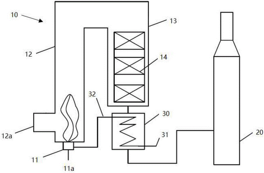
[0030] figure 1 It schematically shows a flue gas treatment device according to Embodiment 1 of the present invention, which is used to treat regenerated flue gas generated by catalyst regeneration in a catalytic cracking process. As shown in the figure, the flue gas treatment device includes: a ...


PUM


Abstract

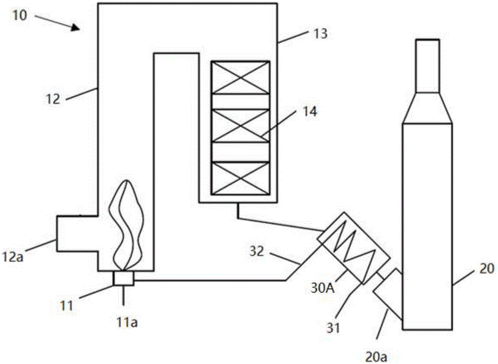
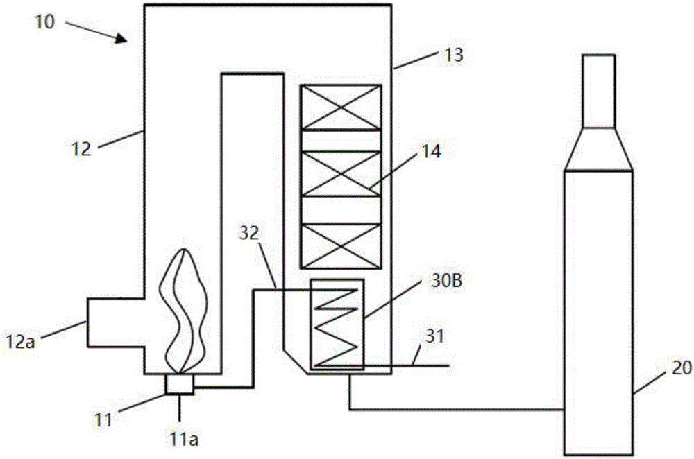
The invention discloses a flue gas treatment device. The device includes a CO boiler, a flue gas desulfurization device and an air preheater, wherein the air preheater is arranged between a steam generating unit of the CO boiler and a flue gas desulfurization device of the CO boiler; the air preheater is used for recycling incineration flue gas waste heat generated by incineration in the CO boiler to preheat combustion-aiding air. According to the flue gas treatment device, by recycling flue gas waste heat generated by incineration in the CO boiler, combustion air in the CO boiler is preheated, the consumption of fuels is significantly reduced, and the efficiency of the boiler is improved. Moreover, cooling work in the desulfurization device can be alleviated, especially for a wet desulphurization device, the water and energy consumption of the desulfurization device can be largely reduced, and energy conservation and emission reduction are achieved.

Description

technical field [0001] The present invention generally relates to petrochemical equipment, and in particular to a flue gas treatment device for petrochemical refinery catalytic cracking equipment. Background technique [0002] According to the content of CO in the flue gas of petrochemical catalytic cracking process, the catalyst regeneration process can be divided into two types: complete regeneration and incomplete regeneration. At present, the incomplete regeneration type is widely used in China, especially for catalytic cracking equipment with large processing capacity. The flue gas generated by catalyst regeneration in the catalyst incomplete regeneration mode (hereinafter referred to as "regenerated flue gas") contains 3%-9% CO. CO in regeneration flue gas is a poisonous gas, and excessive emission is not allowed. Therefore, the regenerated flue gas has to be treated by a flue gas treatment device including a CO boiler. At the same time, the flue gas discharged from...

Claims


Application Information

Patent Timeline
Patent Type & Authority Applications(China)
IPC IPC(8): F23G7/06F22B31/00F23J15/02F23L15/02
CPCF22B31/00F23G7/06F23J15/02F23L15/02F23J2215/20F23G2209/14Y02E20/34
Inventor 程向锋许永伟王伟
Owner LUOYANG MINGYUAN PETROCHEM IND TECH
Learn More