Confluence connector

A connecting mechanism and main tube technology, applied in the sealing of pipes/pipe joints/fittings, branch pipelines, engines, etc., to achieve the effects of improving connection sealing, improving stability, and avoiding leakage

Inactive Publication Date: 2017-05-31
JIAXING HUICHANG PLASTIC IND CO LTD
View PDF7 Cites 1 Cited by
  • Summary
  • Abstract
  • Description
  • Claims
  • Application Information

AI Technical Summary

Problems solved by technology

[0004] Although the above-mentioned solution has many advantages above, the above-mentioned solution does not completely solve the above-mentioned technical problem. Therefore, it is urgent to design a fusion joint that can solve the above-mentioned technical problem

Method used


Image

  • Confluence connector
  • Confluence connector
  • Confluence connector

Examples


Embodiment Construction

[0023] The following are specific embodiments of the invention and in conjunction with the accompanying drawings, the technical solutions of the present invention are further described, but the present invention is not limited to these embodiments.

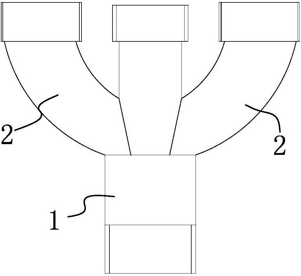
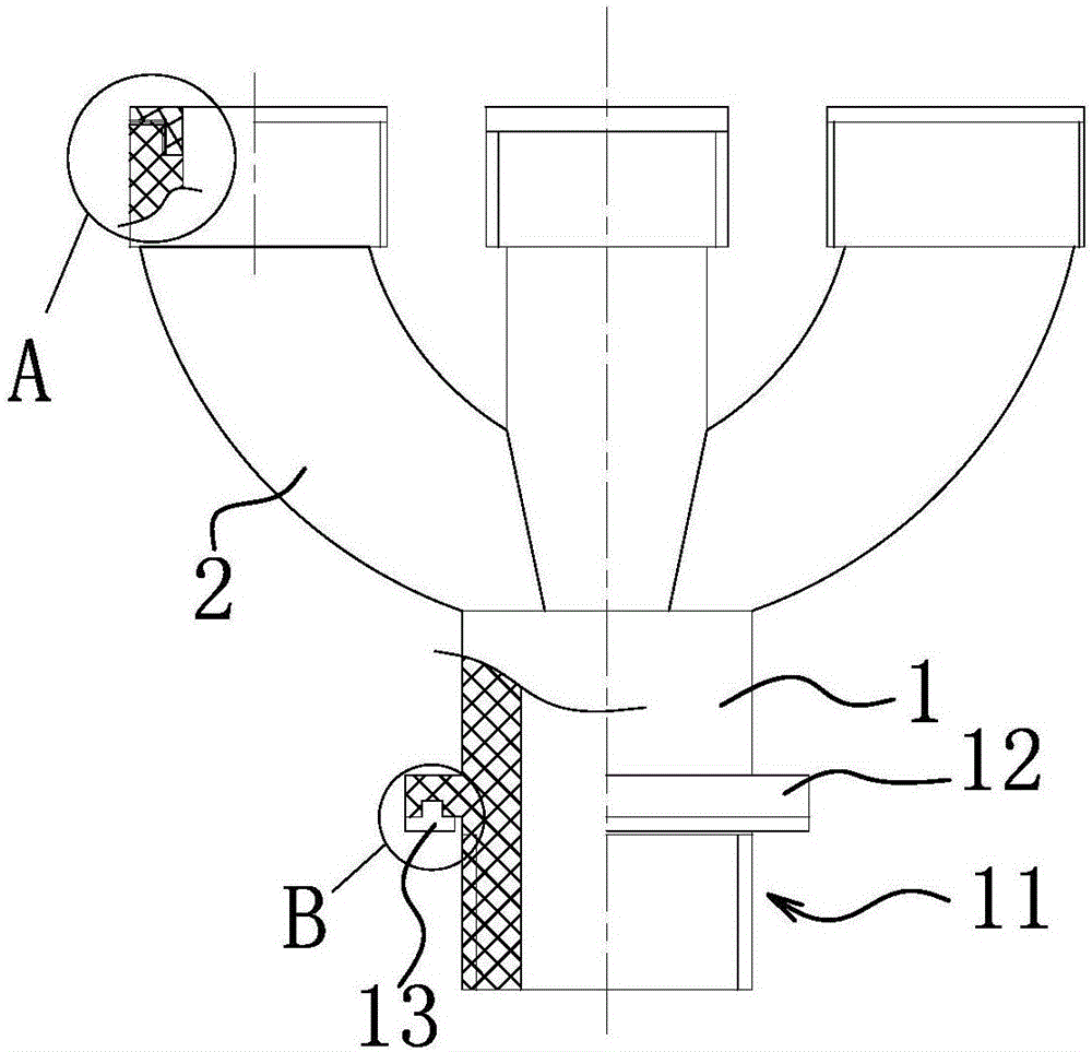
[0024] Such as Figure 1-4 As shown, the confluence joint includes a main pipe 1, and a first sealing connection mechanism 11 is provided at one end of the main pipe 1. Specifically, the first sealing connection mechanism 11 includes an external thread arranged on the outer wall of the main pipe 1 away from the sub-pipe 2. The thread is connected with the internal thread of the connecting screw cap, and the outer wall of the main pipe 1 is also provided with an annular blocking portion 12 at the end of the external thread, and the side of the annular blocking portion 12 close to the external thread is provided with an annular gasket 13 .

[0025] The annular sealing gasket 13 can improve the sealing performance of the contact port...


PUM


Abstract

The invention relates to a confluence connector. The confluence connector comprises a main pipe and three end part sealing ring cushions, wherein a first sealing connection mechanism is arranged at one end of the main pipe; three sub pipes distributed at intervals are connected to the other end of the main pipe; a positioning step is arranged on the inner wall of one end away from the main pipe, of each sub pipe; the three end part sealing ring cushions correspond to the sub pipes in a one-to-one manner; circular rings which can be separately clamped on the corresponding positioning step are separately arranged on the inner side of each end part sealing ring cushion, and each end part sealing ring cushion is fixed to one end away from the main pipe, of each sub pipe through the corresponding circular ring; outer teeth which are arranged in the axial direction of the corresponding circular ring and are in peripheral and uniform distribution are arranged on the outer wall of each circular ring; inner teeth connected with the corresponding outer teeth in a meshing manner are arranged on each positioning step; a plurality of sub pipe teeth which are in peripheral distribution are separately arranged at one end away from the main pipe, of each sub pipe; and sealing ring teeth connected with the corresponding sub pipe teeth in a meshing manner are arranged on one side close to each sub pipe, of each end part sealing ring cushion.

Description

technical field [0001] The invention belongs to the technical field of connectors, in particular to a fusion joint. Background technique [0002] At the socket of the well base, a joint is generally installed to connect the well base or the pipeline. [0003] Current joints generally have multi-way joints, that is, two-way and three-way structures. After the joint is connected and fixed, the tightness of the butt joint is too poor, which leads to leakage and other phenomena. For example, some inventors have disclosed a confluence joint [200820238382.1], which has a pipe body on which at least two pipe joints are integrally provided. The pipe joints of this joint can be on the same plane or not, and the included angle between adjacent pipe joints is 45° or 22.5°, which can be adapted to various situations, and the connection is convenient, and the arrangement of pipes is neat and standardized, which improves the work efficiency. [0004] Although the above-mentioned solut...

Claims


Application Information

Patent Timeline
IPC IPC(8): F16L41/03F16J15/06
CPCF16L41/03F16J15/06
Inventor 李雳
Owner JIAXING HUICHANG PLASTIC IND CO LTD
Why Eureka
Try Eureka