
Patsnap Eureka
For R&D, Patsnap Eureka makes reading and utilizing patents & technical documents easy.
Patsnap Eureka AIR
Designed for self-driven R&D workflows. Generate viable solutions, solve complex R&D challenges, empower your innovation with AI.

Patsnap Eureka Materials
Designed for material experts only. Revolutionize your material R&D, from search, analyze, to developing new materials.

TechResearch
Generate reliable direction feasibility study reports for your R&D in just a few steps.

TechSeek
Discover and master advanced knowledge NOW. Basics, ideas, possibilities, all at once.

TechMind
As an expert in R&D Theories, TechMind can generates customized viable solutions instantly.

TechRisk
Analyze your overall solution with one click, know your potential R&D risks in advance.

TechMonitor
Get weekly tech updates, stay abreast of the latest tech innovations and key insights.
Vacuum valve
A technology for vacuum valves and valve openings, applied in sliding valves, valve details, valve devices, etc., can solve problems such as long working hours and relying on operator experience, and achieve the effects of compact structure, low noise, and small volume
- Summary
- Abstract
- Description
- Claims
- Application Information
AI Technical Summary
Problems solved by technology
Method used
Image


Examples
Embodiment Construction
[0015] The present invention will be described in further detail below in conjunction with the accompanying drawings.
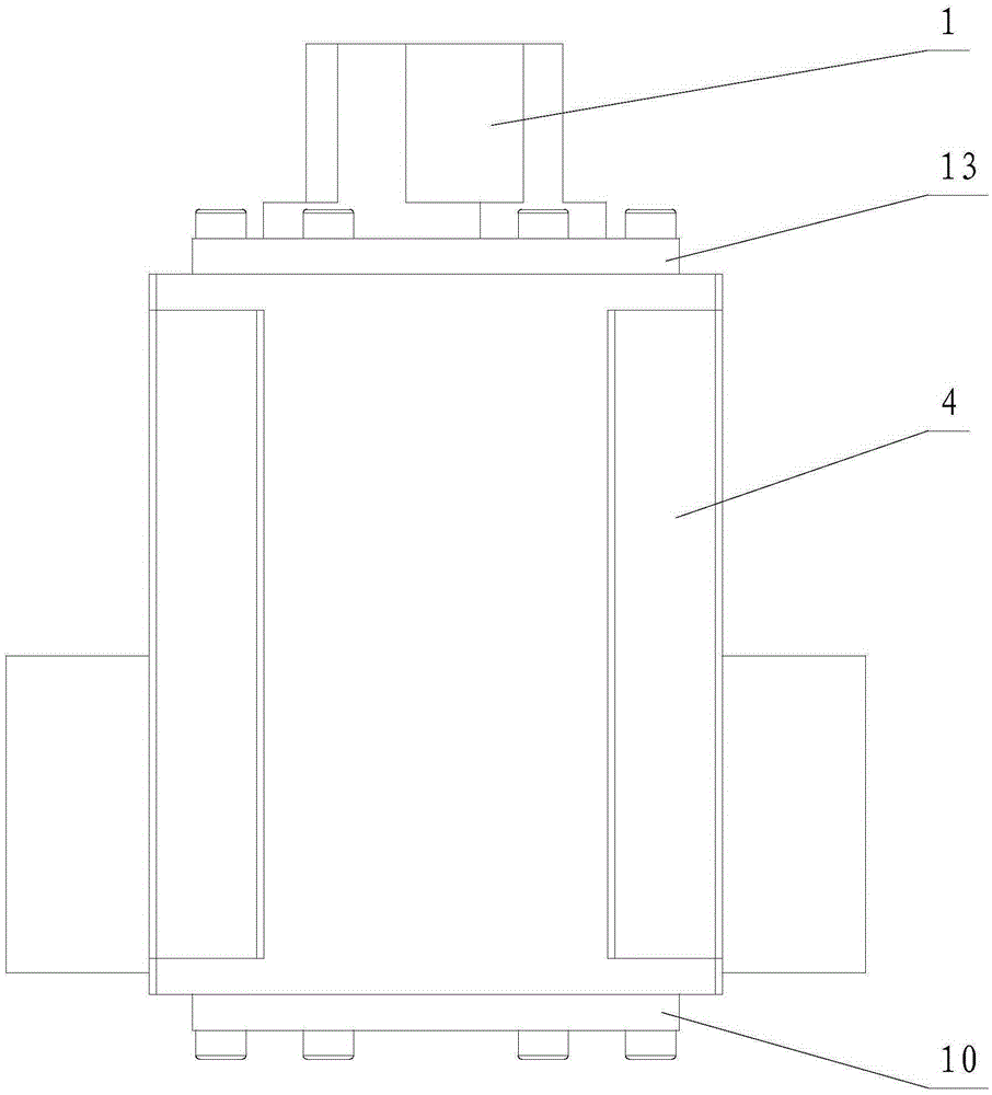
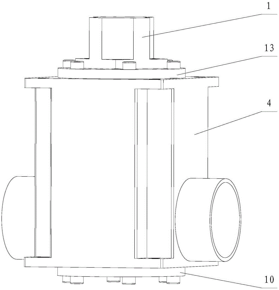
[0016] Such as Figure 1~3 As shown, the present invention includes a linear stepper motor 1, an upper valve cover 13, a valve body 4, a telescopic screw rod 5, a valve seat 7, a lower valve cover 10 and a proximity sensor, wherein the valve body 4 is made of stainless steel, and the nominal The diameter can be 15, 25, 40, 50 and other specifications; the upper and lower ends of the valve body 4 are arranged with valve body sealing rubber rings 9, and the upper valve cover 13 and the lower valve cover 10 are respectively fixed by fastening screws 3 The upper and lower ends of the valve body 4 are sealed with the valve body 4 through the valve cover sealing rubber ring 8 and the valve body sealing rubber ring 9 .
[0017] The linear stepping motor 1 is used as an actuator, and is fixed on the top of the upper valve cover 13, and the seam adopts a small interf...
PUM
 Abstract
Description
Claims
Application Information
 - R&D Engineer
- R&D Manager
- IP Professional
- Industry Leading Data Capabilities
- Powerful AI technology
- Patent DNA Extraction
Browse by: Latest US Patents, China's latest patents, Technical Efficacy Thesaurus, Application Domain, Technology Topic, Popular Technical Reports.
© 2024 PatSnap. All rights reserved.Legal|Privacy policy|Modern Slavery Act Transparency Statement|Sitemap|About US| Contact US: help@patsnap.com