Novel screw pump transmission shaft structure

A transmission shaft and screw pump technology, applied in the direction of rotary motion shaft, pump components, machine/engine, etc., can solve problems such as mechanical maintenance problems, universal joint replacement difficulties, and complex design structures

Inactive Publication Date: 2017-05-31
LUOYANG GENGLI ENG MACHINERY CO LTD
View PDF5 Cites 0 Cited by
  • Summary
  • Abstract
  • Description
  • Claims
  • Application Information

AI Technical Summary

Problems solved by technology

[0002] At present, the screw pumps designed and produced by many domestic manufacturers use universal joints for transmission connection in the transmission design. , still needs to transmit torque, the design structure is complicated, and it is difficult to replace the universal joint, which brings great technical difficulties to the maintenance of the machine

Method used


Image

  • Novel screw pump transmission shaft structure
  • Novel screw pump transmission shaft structure

Examples


Embodiment Construction

[0017] The specific implementation manners of the present invention will be described in detail below in conjunction with the accompanying drawings.

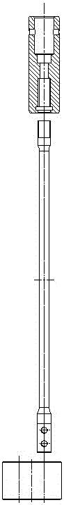
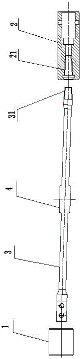
[0018] Such as figure 2 As shown, the novel screw pump drive shaft structure of the present invention includes a rotating sleeve 1 connected to the rotor shaft and a flexible sleeve 2 connected to the driving shaft. The rotating sleeve 1 and the flexible sleeve 2 are not coaxially arranged. And between the rotating sleeve 1 and the flexible shaft sleeve 2, a transmission shaft body is arranged, and the transmission shaft body is an elastic transmission shaft 3, and one end of the elastic transmission shaft 3 is fixedly sleeved in the rotation sleeve 1, and the elastic transmission shaft 3 The other end is fixedly sleeved in the flexible sleeve 2, and the elastic transmission shaft 3 is in an elastic deformation state at this time.

[0019] In this embodiment, the end of the elastic transmission shaft 3 connected to the flexibl...


PUM


Abstract

The invention discloses a novel screw pump transmission shaft structure. The novel screw pump transmission shaft structure comprises a rotating sleeve in transmission connection with a rotor shaft, and a flexible shaft sleeve in transmission connection with a driving shaft; the rotating sleeve and the flexible shaft sleeve are arranged in a disalignment manner; a transmission shaft body is arranged between the rotating sleeve and the flexible shaft sleeve, and is an elastic transmission shaft; one end of the elastic transmission shaft is fixedly sleeved in the rotating sleeve; the other end of the elastic transmission shaft is fixedly sleeved in the flexible shaft sleeve; and at this time, the elastic transmission shaft is located in an elastic deformation state. The novel screw pump transmission shaft structure improves the working efficiency, can transfer higher axial load and torque, and effectively prolongs the service life of the transmission shaft.

Description

technical field [0001] The invention relates to the technical field of screw pump transmission, in particular to a novel screw pump transmission shaft structure. Background technique [0002] At present, the screw pumps designed and produced by many domestic manufacturers use universal joints for transmission connection in the transmission design. , Torque needs to be transmitted, the design structure is complex, and it is difficult to replace the universal joint, which brings great technical difficulties to the maintenance of the machine. [0003] Such as figure 1 As shown, it is a structural schematic diagram of the existing screw pump drive shaft, which includes a rotating sleeve connected to the rotor shaft and a flexible sleeve connected to the driving shaft. The rotating sleeve and the flexible sleeve are arranged differently. When the transmission shaft body is coaxial with the flexible bushing, it is not coaxial with the rotating sleeve, and the left end of the tra...

Claims


Application Information

Patent Timeline
IPC IPC(8): F04C15/00F16C1/08F16C1/02
CPCF04C15/0061F16C1/02F16C1/08
Inventor 卜志强卜宜鸣王宏凡
Owner LUOYANG GENGLI ENG MACHINERY CO LTD
Why Eureka
Try Eureka