Speed reducer

A technology of reducer and connector, which is applied in the direction of gear transmission, belt/chain/gear, mechanical equipment, etc. It can solve the problems of insufficient running precision, large vibration amplitude, frequent maintenance, etc., and achieve high precision of zero-gap transmission, The effect of good practical performance and high stability torque transmission

Pending Publication Date: 2019-11-19
HONGFUJIN PRECISION ELECTRONICS (ZHENGZHOU) CO LTD +1
View PDF7 Cites 0 Cited by
  • Summary
  • Abstract
  • Description
  • Claims
  • Application Information

AI Technical Summary

Problems solved by technology

However, the general reducer is not only large in size, but also has problems such as large backlash and insufficient running accuracy during operation, resulting in short service life, frequent maintenance, large vibration amplitude and high noise, etc. It is necessary to improve

Method used


Image

  • Speed reducer
  • Speed reducer
  • Speed reducer

Examples


Embodiment Construction

[0031] The present invention will be described in detail below in conjunction with the accompanying drawings.

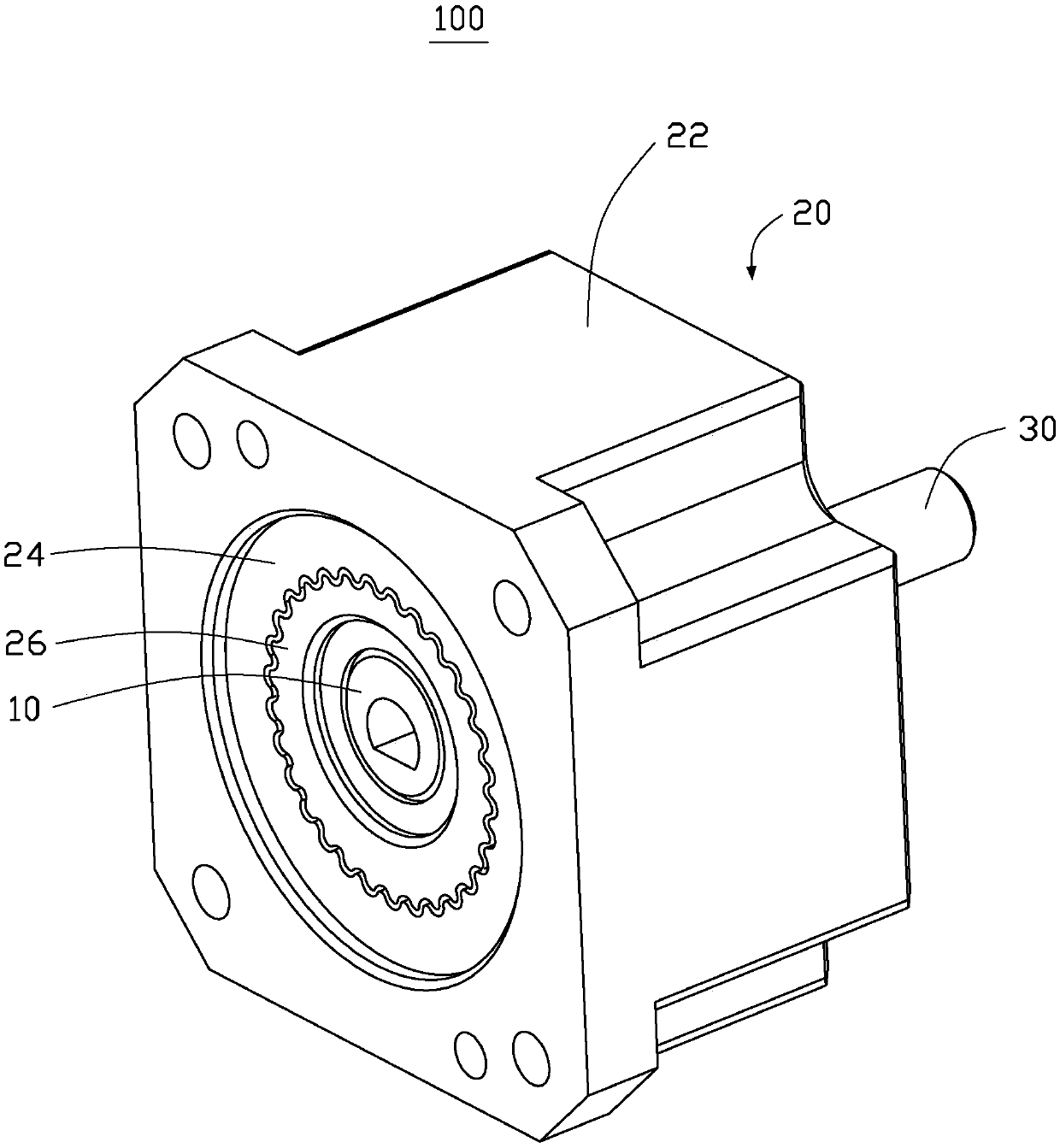
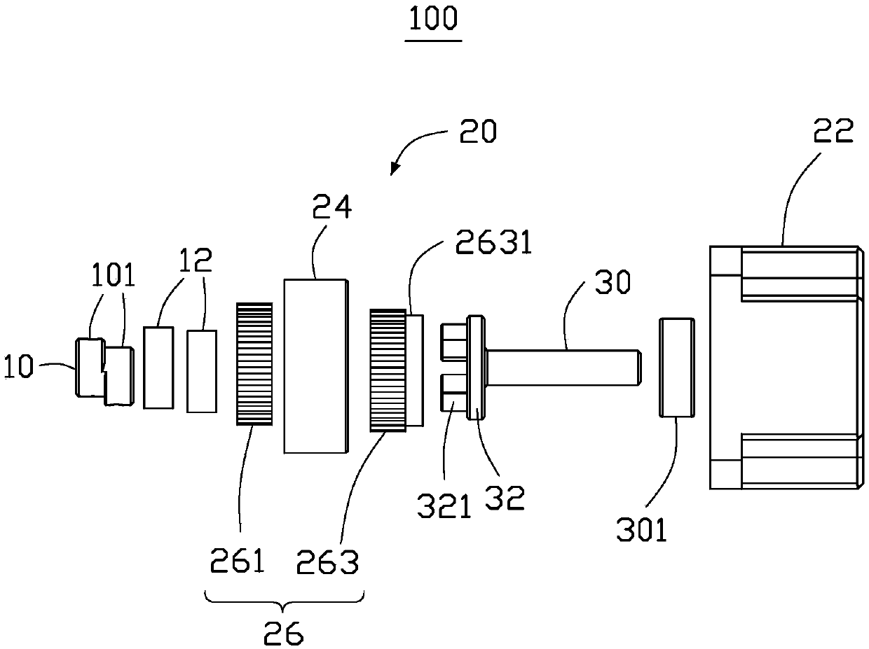
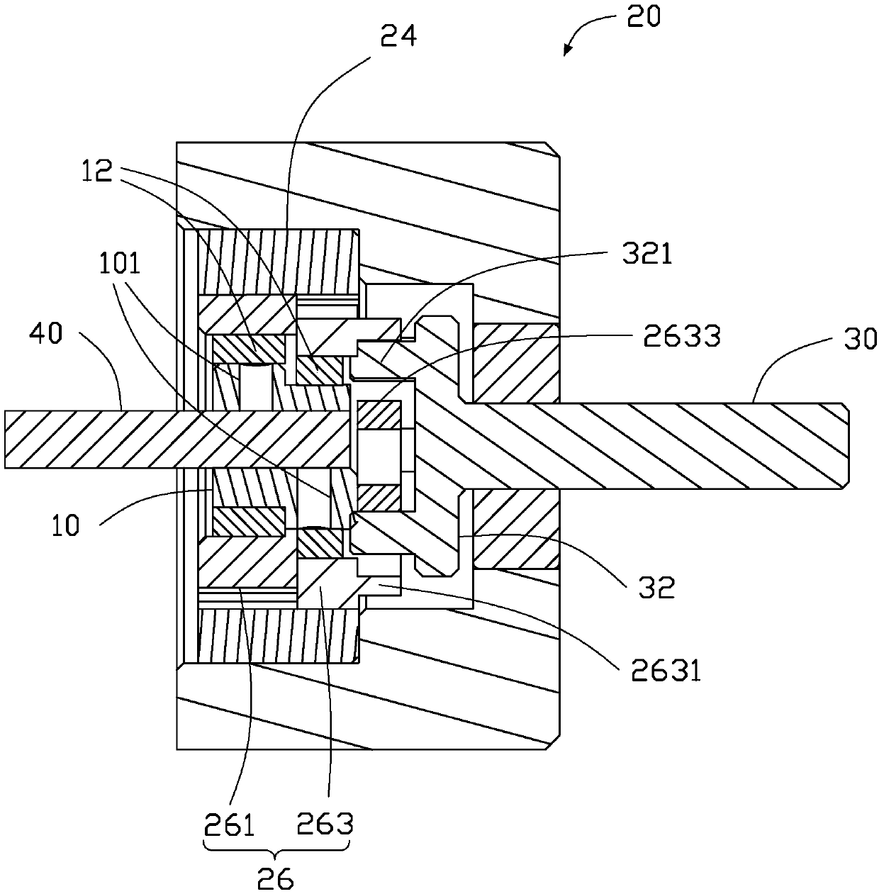
[0032] see figure 1 and figure 2 , figure 1 It is a three-dimensional schematic view of a specific embodiment of the reducer of the present invention. figure 2 yes figure 1 Disassembled three-dimensional schematic diagram of the reducer. figure 1 The reducer 100 described in the above includes an input shaft 10, a gear unit 20, and an output shaft 30. The input shaft 10 and the output shaft 30 are respectively located on both sides of the gear unit 20, and together form a small volume and a compact structure. The reducer 100. see again figure 2 , the input shaft 10 is an eccentric shaft, and the eccentric shaft is connected with the gear unit 20 . The gear unit 20 includes a housing 22, an external gear 24 and at least two internal gears 26, the external gear 24 is arranged in the housing 22, and the external gear 24 is internally connected to the internal ...


PUM


Abstract

The invention discloses a speed reducer. The speed reducer comprises an input shaft, a gear set and an output shaft; the input shaft is an eccentric shaft; the eccentric shaft is connected with the gear set; the gear set comprises a shell, an outer gear and at least two inner gears; the outer gear is arranged in the shell, and is internally connected with the inner gears; one side of each inner gear is in shaft connection with the input shaft; the other side of each inner gear is connected with a connecting column of the output shaft; through driving of the input shaft, the inner gears are continuously engaged with the outer gear; and through connection of the connecting column, the transmission of the output shaft and the inner gears is continuously maintained. Through shaft connection ofthe input shaft with the inner gears and transmission of the connecting column, the speed reducer achieves zero-gap conduction and high-precision and high-stability torque conduction, and excellent practicability is achieved.

Description

technical field [0001] The invention relates to a speed reducer. Background technique [0002] At present, industries such as precision industrial processing, automation equipment, and robots all use reducers to match speed and transmit torque. Reducers are widely used in modern machinery. The reducer uses the electric motor, internal combustion engine or other high-speed running power to achieve the purpose of deceleration through the gear with a small number of teeth on the input shaft of the reducer meshing with the large gear on the output shaft. Generally, the reducer uses the transmission ratio gear principle for deceleration, that is, the gear ratio of the large and small gears is set to achieve the ideal deceleration effect. However, the general reducer is not only bulky, but also has problems such as large backlash and insufficient running accuracy during operation, resulting in short service life, frequent maintenance, large vibration amplitude and high noise, etc...

Claims


Application Information

Patent Timeline
Patent Type & Authority Applications(China)
IPC IPC(8): F16H1/20
CPCF16H1/206F16H1/32F16H1/227F16H2001/327F16H2001/323
Inventor 刘宇青杨炜达苏柏霖康杰朋张留明李素敏王光星赖婕
Owner HONGFUJIN PRECISION ELECTRONICS (ZHENGZHOU) CO LTD
Why Eureka
Try Eureka